A Split Phase Inverter is designed to match the standard residential power system used in North America, where both 120V and 240V electricity are required. It provides a practical solution for running everyday household appliances as well as high-power equipment within a single integrated system.
To better understand how a Split Phase Inverter operates, we will break down its key components and working principles step by step. This includes the roles of L1, L2, and Neutral, the different wiring configurations for 120V and 240V output, and how these modes are used in real residential applications.
What Is a Split Phase Inverter?
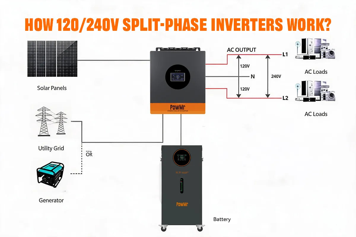
A Split Phase Inverter is a power electronic device that converts direct current (DC) into alternating current (AC) while simultaneously producing two output voltages that are 180 degrees out of phase. It typically provides three terminals: L1, L2, and N (neutral). The voltage between L1 and N is 120V, and the voltage between L2 and N is also 120V, while the voltage between L1 and L2 is the sum of the two, resulting in 240V.
This design is primarily intended to meet the electrical standards of regions such as North America and Japan that use split-phase power systems, allowing a single inverter to supply both 120V and 240V appliances simultaneously.
Terminal Explanation: L1, L2, and N
In a split-phase inverter or a 120V/240V split-phase power system, you will typically see three main output terminals: L1, L2, and N (Neutral). Understanding the function of these terminals is essential for correct installation and safe operation of the system.

L1 and L2 are two live (hot) wires that are 180° out of phase with each other. In a standard split-phase system, L1 to N provides 120V, and L2 to N also provides 120V. However, when measuring between L1 and L2, the voltage is 240V. This configuration allows the system to support both standard 120V loads and higher-power 240V appliances.
N (Neutral) serves as the return path for current and provides a stable reference potential. In 120V loads, the neutral line carries the return current. For 240V loads, the neutral is typically not used, as the current flows directly between L1 and L2.
How Does a Split Phase Inverter Work?
The function of a split phase inverter is to convert DC power generated by photovoltaic panels or batteries into usable AC power for residential applications, while providing a split-phase output of 120V/240V. As shown in the diagram, the inverter can supply power to 120V household loads such as lighting, televisions, and standard outlets. At the same time, it can also support 240V high-power loads, including air conditioners, washing machines, electric water heaters, and EV charging stations.

By simulating the split-phase structure of the utility grid, the inverter establishes a standard voltage relationship between L1, L2, and N, enabling a single system to support both low-voltage and high-voltage appliances. When grid power is available, it can also work in coordination with the utility supply, providing a more stable and flexible power solution for the home.
The Three Wiring Modes for 120V/240V Split-Phase Output
A 120V/240V split-phase inverter can be wired in different ways depending on the load requirements of the system. In general, there are three common wiring modes: Pure 120V Load Mode, Simultaneous 120V & 240V, and Simultaneous 120V & 208V Hybrid Load Mode.
The main difference between these modes is not the inverter’s power output itself, but how L1, L2, and N (neutral) are connected and how the loads are distributed. For residential solar systems, off-grid power systems, and home backup power solutions, choosing the right wiring mode helps the inverter match real-world energy needs more efficiently.
The following examples use the PowMr 8KW 120V/240Vac Split Phase Inverter to demonstrate the three wiring modes for 120V/240V split-phase output.
Mode 1: 120V/240V Split-Phase Output Mode
In 120V/240V Split-Phase Mode, the system is designed to support both 120V and 240V appliances simultaneously, providing flexible power distribution for residential and off-grid applications.
The 240V load is connected between L1 and L2, while 120V loads are connected between L1 (or L2) and Neutral (N), allowing the system to power a wide range of devices such as lights, household appliances, water pumps, air conditioners, and electric water heaters at the same time.
120V/240V Split-Phase Output Diagram

This diagram shows the standard 120V/240V split-phase inverter output. In this mode, L1 to N provides 120V, L2 to N provides 120V, and L1 to L2 provides 240V. This is the most common residential electrical configuration in North America, making it ideal for both 120V household appliances and 240V high-power loads. It is also the typical output structure used in residential solar systems, off-grid power systems, and home backup power solutions.
Mode 2: Pure 120V Load Mode
In Pure 120V Load Mode, the system supplies only 120V appliances, such as lighting, TVs, routers, outlets, and small household electronics. In this mode, the inverter is configured as a single-phase 120V output, making it ideal for homes or off-grid systems that do not require any 240V loads. It offers a simple and practical wiring setup for basic power needs.
120V Single-Phase Output Diagram

This diagram shows the inverter operating in Single-Phase Mode. In this configuration, L1 and L2 are internally paralleled, so the inverter no longer provides standard 120V/240V split-phase output. Instead, it delivers a single 120V output at full inverter capacity. This mode is ideal for applications that only require 120V loads, such as lighting, outlets, electronics, and small household appliances.
Mode 3: Simultaneous 120V & 208V Hybrid Load Mode
This is a flexible wiring mode for a split-phase inverter that supports both 120V loads and 208V loads at the same time. Standard household appliances can draw 120V from L1-N or L2-N, while compatible higher-power equipment can draw 208V between L1 and L2.
This hybrid setup is useful in residential solar systems, off-grid power systems, and mixed-load applications where both 120V and 208V AC power are required. It provides a practical and efficient solution for systems that need multiple output voltages in one configuration.
120V/208V Hybrid Output Diagram

This diagram shows the 120V & 208V hybrid load mode. In this configuration, standard 120V loads can be connected from L1 to N or L2 to N, while higher-power equipment can draw 208V AC power between L1 and L2.
This setup is useful in systems that need to support both everyday 120V appliances and 208V loads at the same time. It provides a flexible and efficient solution for commercial power systems, off-grid inverter applications, and split-phase inverter output configurations.
Output Voltage Adjustment Settings
After understanding how split-phase inverter systems work (see How 120V/240V Split-Phase Inverters Work), Output Voltage Adjustment Settings lets you align the inverter with local grid standards and load requirements.
The 8KW Split Phase All-in-One Inverter (POW-SunSmart 8KP) provides two hot lines (L1 and L2) and one Neutral (N). Instead of selecting a fixed output voltage, the inverter's output characteristics are determined by two configurable parameters:
- AC Output Voltage – Sets the line-to-neutral voltage (L1–N and L2–N) within a range of 100–130V, adjustable in 1V increments.
- Grid Type – Defines the phase relationship between L1 and L2 by selecting a phase angle of 180°, 120°, or 0°.
These two settings work together to determine the inverter's final output characteristics. The AC Output Voltage defines the voltage supplied from L1 to Neutral and L2 to Neutral, while the Grid Type determines the phase relationship between the two hot lines. Different combinations are used to match regional electrical standards and the requirements of specific applications.
Applications of a Split Phase Inverter
A split phase inverter is essential for applications requiring both 120V and 240V AC power simultaneously. Key use cases include:
Residential Power Supply (North American Standard)
This is the primary application. The inverter directly replaces the grid transformer, providing 120V for lighting and outlets and 240V for heavy loads like air conditioners, ovens, dryers, and EV chargers. It is the core component of off-grid or solar-powered home systems.
Electric Vehicle (EV) Vehicle-to-Load (V2L)
Integrated into some EVs, the split phase inverter converts high-voltage battery DC power into 120V/240V AC, powering common appliances for camping, outdoor work, or home emergency backup.
Recreational Vehicle (RV) and Marine Systems
A split phase inverter is mandatory only if you need to operate 240V heavy-duty appliances(e.g., high-power AC units, dryers) or perform Level 2 EV charging on your RV or boat. For 120V-only devices, a standard single-phase inverter suffices.
Off-Grid Solar and Energy Storage Systems
As the heart of an off-grid solar power station, the inverter converts DC power from batteries or solar panels into split-phase 120V/240V AC power, supplying an entire building.
Split Phase Inverter vs. Single Phase Inverter
After understanding how 120V/240V split-phase inverter systems work, it becomes clear that Split Phase Inverters and Single Phase Inverters differ significantly in structure and application.
Taking the 8KW 48Vdc Split Phase All in One Inverter (SKU:POW-SunSmart 8KP) split-phase inverter as an example, it is designed with a 120V/240V split-phase architecture. It generates two 180° phase-shifted outputs (L1 and L2), providing both 120V and 240V power simultaneously. This makes it ideal for North American residential systems, RV applications, and off-grid solar setups, as it can power both standard household appliances and high-power devices such as air conditioners, water pumps, and electric heaters.
In contrast, the 4500W 110Vac Single Phase All In One Inverter (SKU:POW-LVM4.5K-24V) Single-Phase All-in-One Inverter provides a single 120V line (L)-to-neutral (N) output. Unlike a split-phase inverter, it cannot power both 120V and 240V loads simultaneously from a single inverter.
In practical applications, split-phase inverters offer greater load flexibility and compatibility, while single-phase inverters are better suited for standardized, single-voltage systems.
Key Comparison Table
| Comparison Item | POW-SunSmart 8KP (Split Phase Inverter) | POW-LVM4.5K-24V (Single Phase Inverter) |
|---|---|---|
| Output Structure | 120V/240V split-phase (L1 + L2 + N) | Single-phase (L + N) |
| Voltage Capability | Supports both 120V and 240V outputs | 120V line (L) -to-neutral (N) output |
| Load Capability | Powers both 120V and 240V loads | Powers 120V loads only |
| Typical Applications | Homes, RVs, off-grid systems | Homes, cabins, RVs with 120V loads |
| Typical Devices | Air conditioners, well pumps, water heaters, household appliances | Standard household appliances |
| System Flexibility | High | Moderate |
| Installation Complexity | Medium | Lower |