Solar Inverters
- Power inverters, inverter chargers, and hybrid models
- Suitable for off-grid, backup, and grid-tie systems
- Reliable performance with flexible configurations
Understanding Different Types of Solar Inverters
Learn how power inverters, off-grid systems, all-in-one inverter chargers, and hybrid inverters work for residential, RV, backup, and solar storage applications.
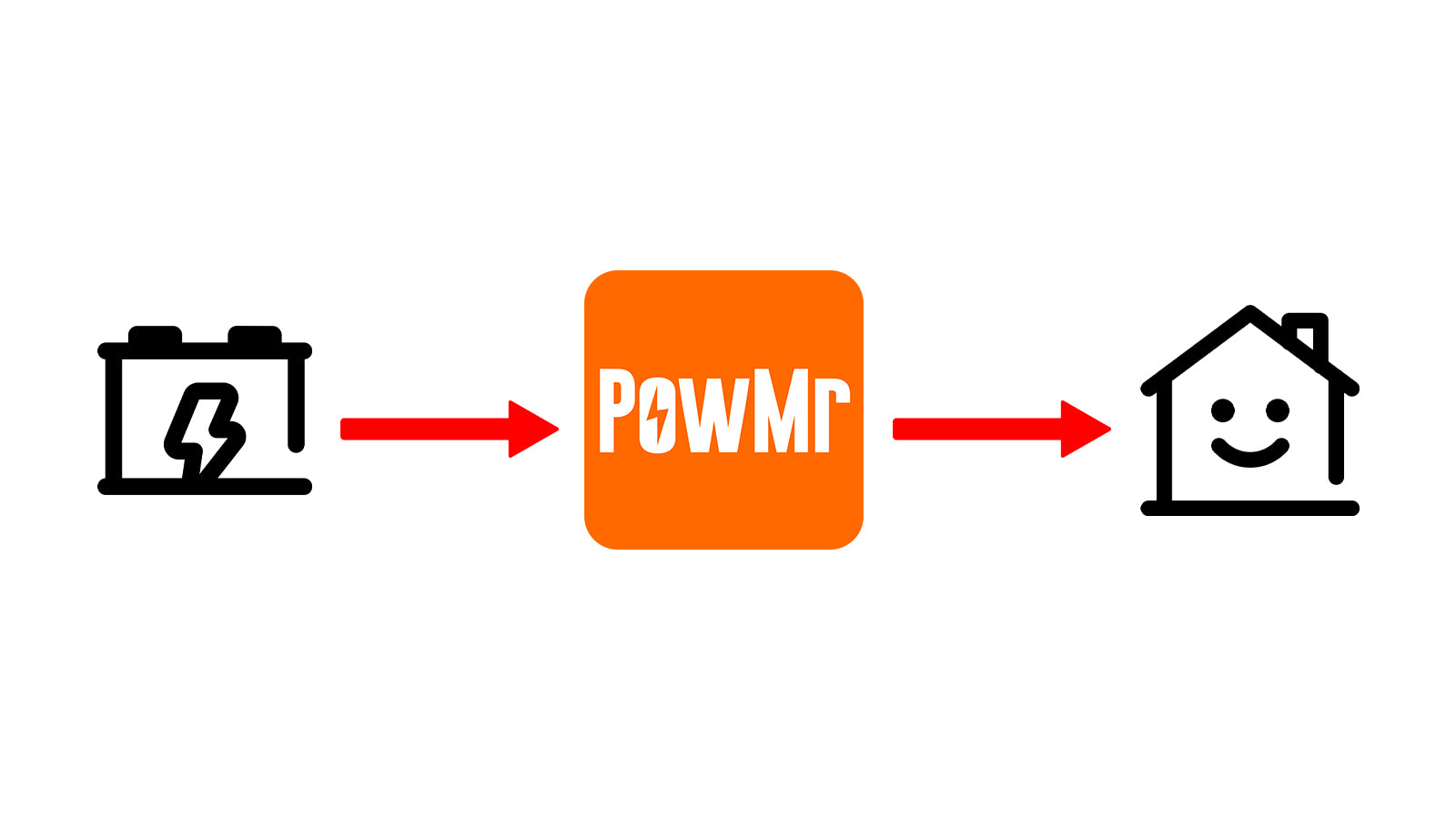
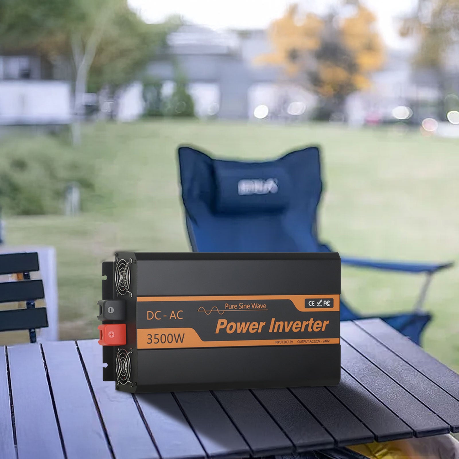
Power Inverters
The most basic inverter converts battery DC to AC. Suitable for RVs, boats, or basic standalone off-grid systems.
No
No
Single Phase
No
Off Grid Inverters
Solar inverters without batteries convert DC from solar panels into AC directly. Low initial cost, budget-friendly.
Yes
No
Single Phase
No
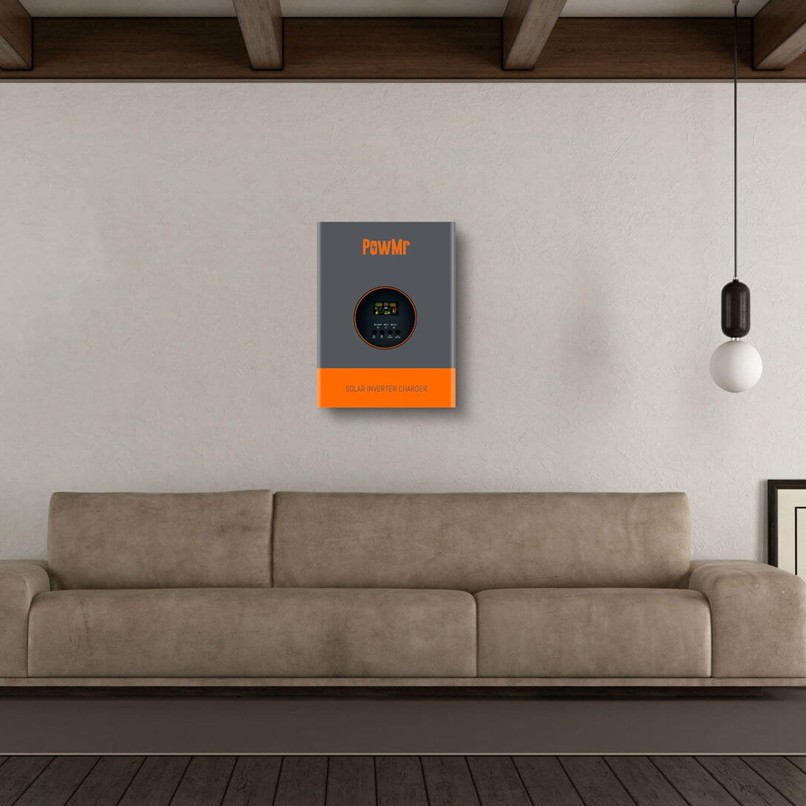
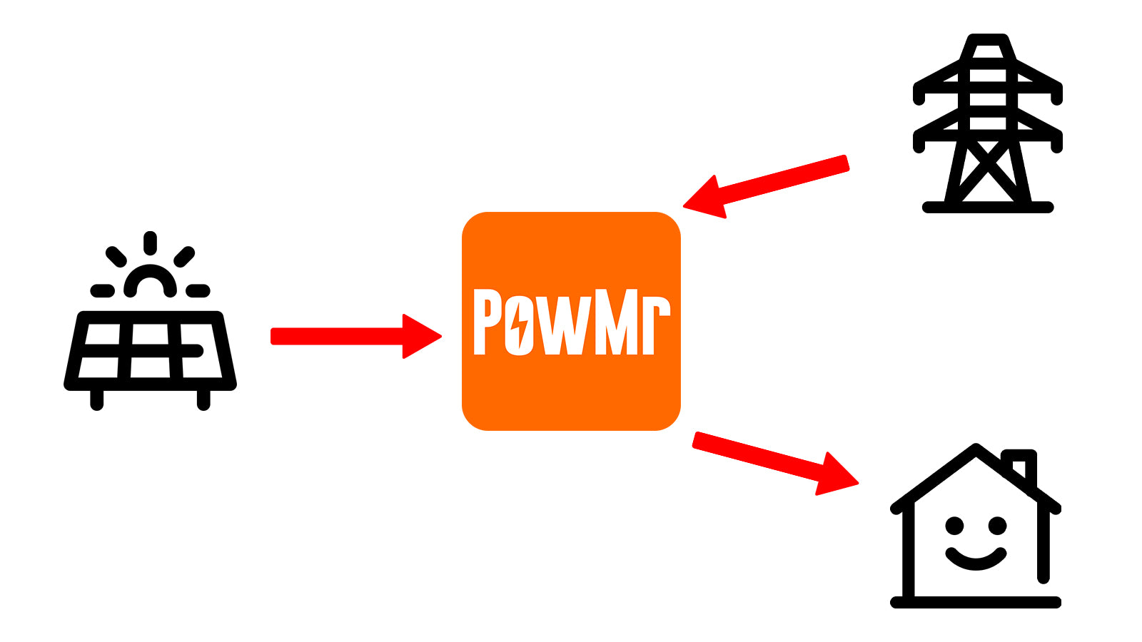
All in One Inverters
Inverter chargers combine MPPT solar charge controller, AC charging, and inverter, with programmable power priorities.
Yes (Dual MPPT Optional)
Solar Panel
Grid
Generator
Single / Split Phase
No
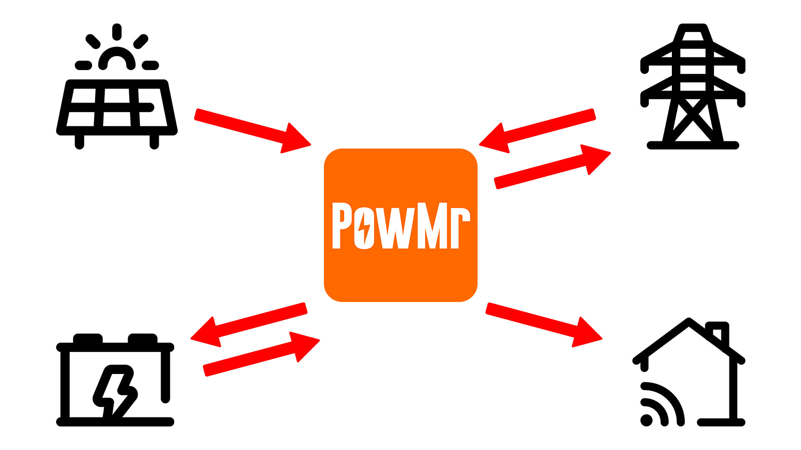
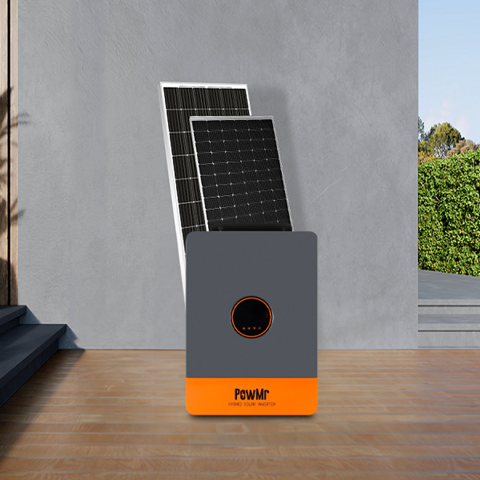
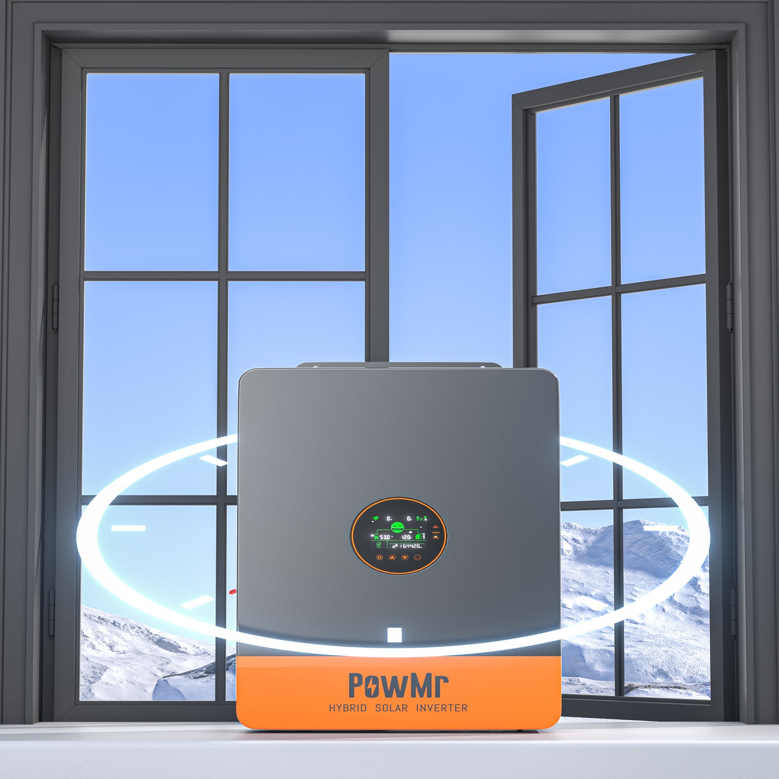
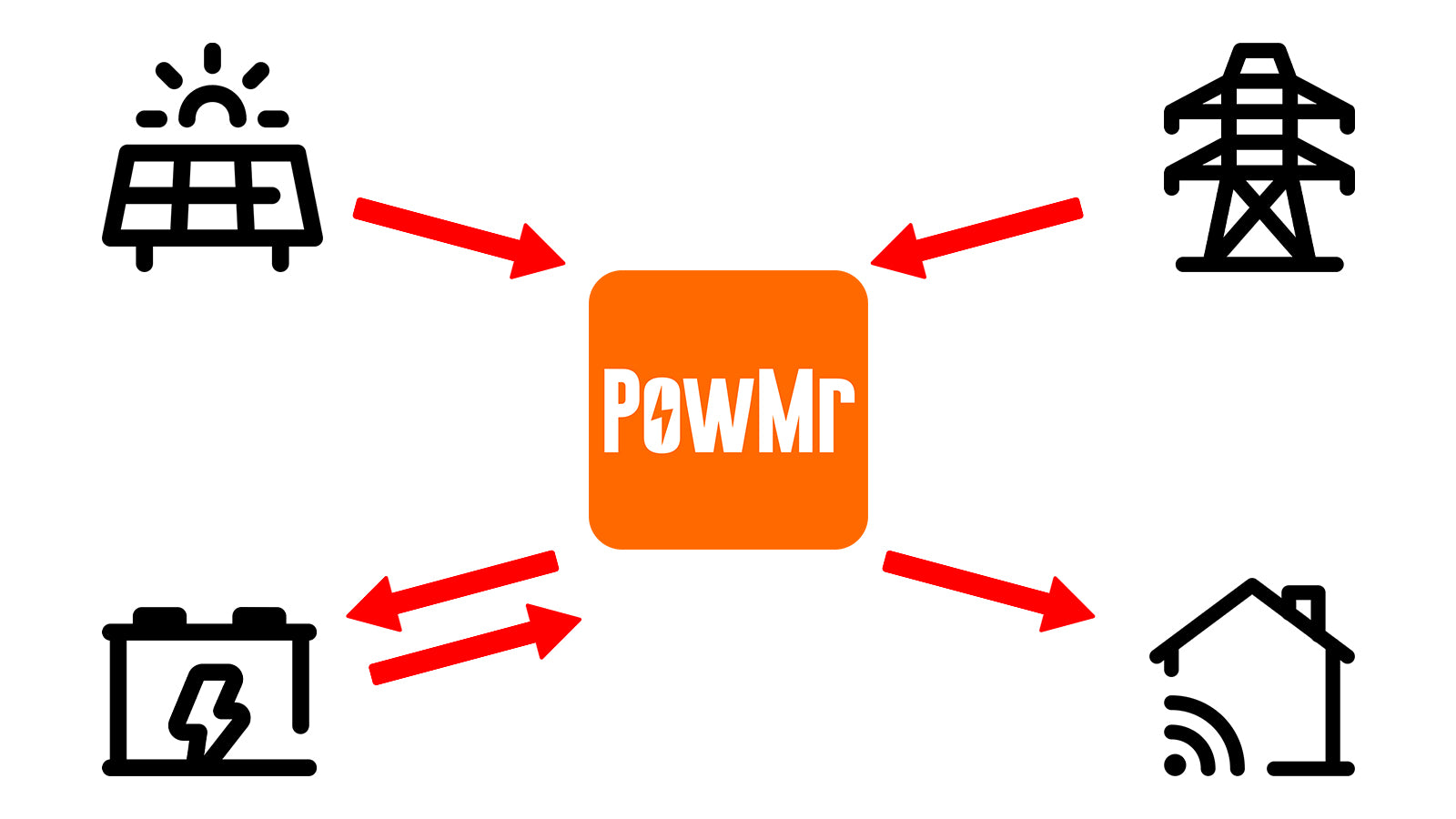
Hybrid Inverters
Manages power flow between PV, battery, and grid, enabling smart grid interaction for energy savings and gains.
Yes (Dual MPPT Optional)
Solar Panel
Grid
Generator
Single / Split / Three Phase
Yes

Turn Your Roof Into A Power Plant
Solar can be a smart way to cut your monthly bills and make a big impact on the environment!
All In One Inverters
Do you know what is an All-in-one inverter? It is also known as an All-in-One system that has the three most crucial elements for energy production. However, the components are also necessary in any device. These are the battery charger, inverter, and the Maximum Point Tracker solar charger controller. The device makes the power system more efficient because it reduces the components needed. for the individual to save money and space. Installation challenges are minimized, and it lowers other associated expenses as well.
Excellent Power Conversion
The all-in-one inverter is a reliable solution for providing credible power conversion. The energy is lost and transported to the devices efficiently. Moreover, the MPPT device will convert DC into AC power successfully. You can use it anywhere on and off the grid to use appliances. The peace of mind is incredible because the energy source is reliable.
Excellent results
When an all-in-one inverter uses solar power energy, it optimizes the user of the devices. The system will monitor the sun’s intake and regulate the voltage automatically. The technology studies the power of coming in and exiting from the solar panels. MPPT ensures excellent extraction of energy and its conversion to electricity.
Battery charging
The all-in-one inverter technology is designed to be safe. It is an efficient internal system that complements the battery and appliances. The technology will prevent battery explosions by maintaining it excellently. Moreover, MPPT will elongate the battery’s life. It will improve the performance. As a result, the feature positively influences the power system.
Versatility
Lastly, an all-in-one inverter is a trending solution to your energy problems. It converts power into electricity without waste. Batteries can stay charged for a long time. In addition, the solar power system becomes easier to manage. It is an integrated solution that is improving user experience worldwide.

Get A Little Sunshine In Your Life
Making people rethink their electric bill (in a good way) with these cool solar installations.
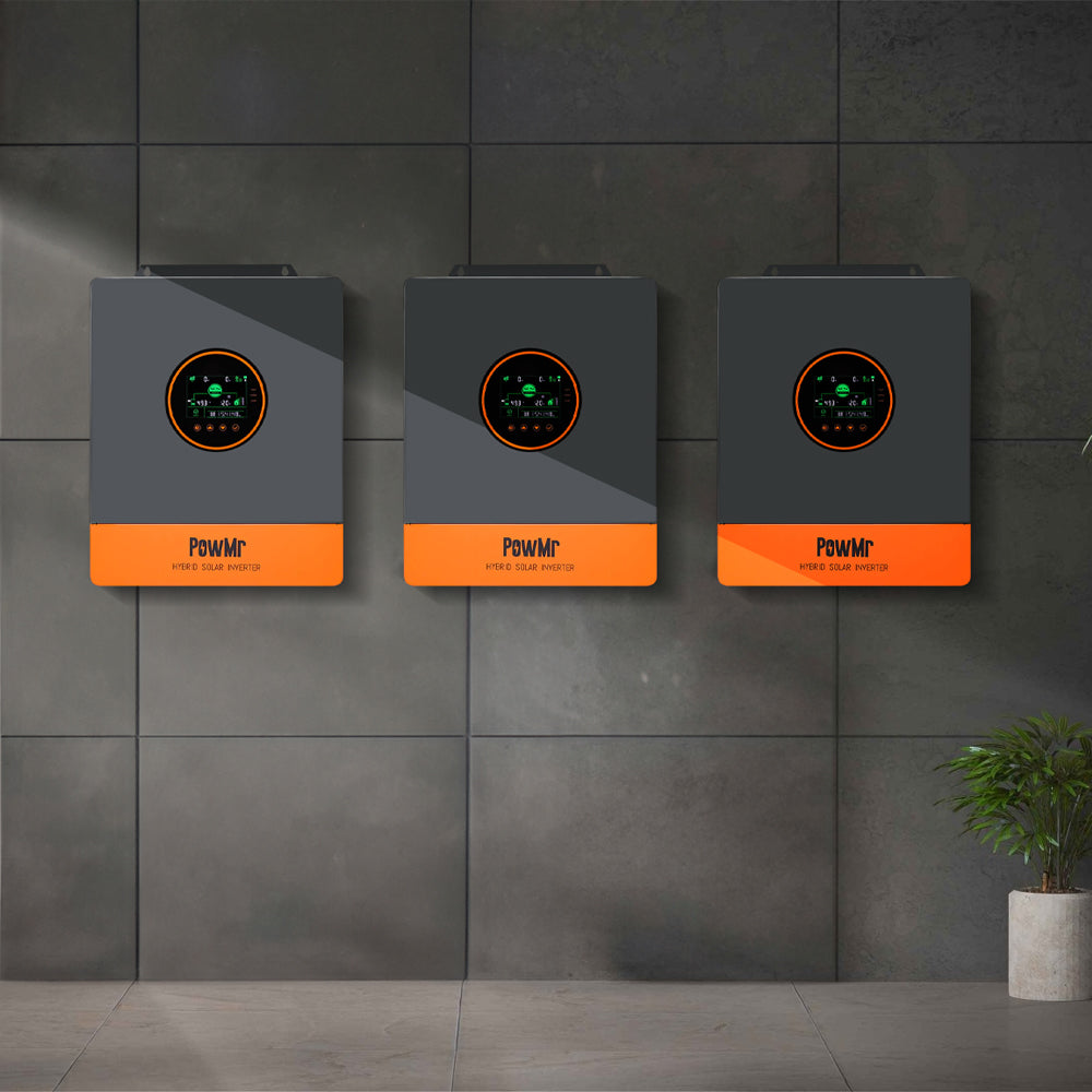
Parallel inverters
Refer to a configuration in which two or more inverters are connected in parallel to work together as a unified power source.
This setup allows the combined system to deliver higher total output power, improve reliability, and support more complex applications such as three-phase power supply or load sharing. In a parallel system, each inverter must synchronize its voltage, frequency, and phase with the others to ensure stable and efficient operation.
Modern inverters often include built-in communication protocols or master-slave controls to manage synchronization and load distribution automatically.
Scalability
Parallel systems allow you to start with a small number of inverters and gradually increase the system's total capacity by adding more units as needed. This makes it easy to expand the system in the future without replacing existing components.
Redundancy and Reliability
In the event that one inverter fails, the remaining inverters can continue operating, minimizing downtime and maintaining power supply. This built-in redundancy improves the overall reliability of the system, especially in critical power applications.
Load Sharing and Efficiency
When inverters operate in parallel, the load is automatically distributed across all connected units. This balanced load sharing helps prevent overloading any single inverter, reduces heat buildup, and improves the overall energy efficiency and lifespan of each unit.
System Flexibility and Versatility
Parallel inverters can be configured to support both single-phase and three-phase systems, making them adaptable to a wide range of residential, commercial, or industrial applications. This flexibility also simplifies system design for complex energy needs.