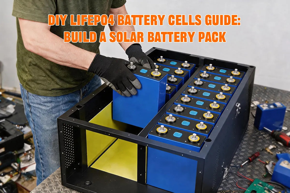
Building your own LiFePO4 (lithium iron phosphate) battery pack is a cost-effective and flexible energy storage solution. Compared to pre-built batteries, a DIY build typically saves 30–50%, while letting you customize voltage and capacity and choose your own cells and BMS.
This guide walks you through the full process—from material selection, batter cell matching, and series/parallel configuration to BMS wiring and solar system integration—using a 12.8V 100Ah pack (4 × 3.2V cells in series) as the example. Follow the steps below to build a safe, durable DIY solar battery pack for off-grid, RV, or home backup use.
Materials and Tools Needed for a DIY LiFePO4 Battery Pack
Materials
To build a DIY LiFePO4 battery pack, start with four Grade A prismatic LiFePO4 battery cells (3.2V each) in a 4S configuration for a 12.8V 100Ah solar energy storage battery. You'll also need a matched battery management system (BMS), busbars, screws, epoxy insulation plates, fiber tape, output cables, and a fuse or breaker. An NTC temperature probe and Bluetooth module are recommended for monitoring via the Smart BMS app.
Essential Tools
A multimeter and internal resistance meter are essential for voltage checks and cell matching (keep internal resistance variation within 5%). You'll also need hex wrenches or a torque screwdriver for busbar connections, plus a bench power supply or charger for the first charge andBMS SOC calibration. Wear insulated gloves and safety glasses, and work in a clean, dry area.
LiFePO4 Cell Selection and Matching
When building a DIY LiFePO4 (lithium iron phosphate) battery pack, the first step is choosing the right cells. You need to confirm three core parameters:cell voltage capacity, and number of cells in series
- Cell voltage:LiFePO4 has a nominal voltage of3.2V
- Capacity: Common options include 100Ah and 280Ah — this determines how much energy the pack can store
- Series count: This determines your system voltage
This guide uses a 12.8V 100Ah solar energy storage battery as the example, configured as 4S — four 3.2V cells in series (4 × 3.2V = 12.8V). For a 48V energy storage system, you’ll need a 16S configuration (16 cells in series).
We recommend sourcing Grade A prismatic LiFePO4 cells from the same batch and specification whenever possible. That makes battery cell matching easier later and improves overall pack consistency.
Match Cell Internal Resistance and Voltage
After selecting the LiFePO4 cells, the next step is to test and match them before assembly.Even cells from the same batch and the same model can differ slightly in voltage, capacity, and internal resistance. If you wire them into a DIY lithium battery pack without screening, those small differences grow over every charge and discharge cycle.
Voltage matching:
Voltage matching ensures all cells start at a similar state of charge (SOC) before assembly. If one cell sits noticeably higher than the rest, it will hit its upper voltage limit first during charging. The BMS may then cut off charging early, leaving the pack underfilled. During discharge, the lowest-voltage cell can hit bottom first — raising the risk of over-discharge.
Internal resistance matching :
Internal resistance matching keeps each cell carrying a similar current and generating a similar amount of heat. Lower-resistance cells take on more current; higher-resistance cells run hotter. Over time, that imbalance pulls the whole pack out of sync.
Before assembling any DIY LiFePO4 battery pack, cell internal resistance and voltage matching are essential steps that directly affect safety, consistency, and cycle life.
LiFePO4 Cell Internal Resistance Matching Method
Before testing, let cells rest for 1–2 hours so voltage and internal resistance readings stabilize. Work in a dry environment and ensure solid terminal contact throughout.
Basic steps:
- On the internal resistance meter, choose LiFePO4 / lithium battery mode. Readings are typically shown in mΩ (milliohms).
- Touch the positive and negative probes firmly to each cell’s terminals or M6 studs. Keep contact surfaces clean and secure — loose contact will inflate readings.
- Measure and log each cell’s internal resistance. At the same time, use a multimeter to record its voltage.
- Measure each cell 2–3 times and average the results to reduce random error.
- From your available cells, choose the four (or sixteen) with the closest internal resistance and voltage values to form your battery pack.
Testing tips:
- Test under the same temperature and SOC conditions (around 50% charge, or after new cells have rested)
- Follow the same test sequence every time for easier comparison
- Flag cells with unusually high or low resistance — don’t force them into the same pack
Keep Internal Resistance Deviation Within 5%
After completing all internal resistance tests, calculate the average resistance for the group and verify that every cell meets the matching standard.
Average internal resistance:
Ravg = (R1 + R2 + R3 + R4) ÷ n
Per-cell deviation rate:
Deviation Rate = |Ri − Ravg| ÷ Ravg × 100%
Matching requirement:
|Ri − Ravg| ÷ Ravg × 100% ≤ 5%
Example
| Cell | Internal Resistance (mΩ) | Deviation Rate | Pass? |
|---|---|---|---|
|
Cell 1
|
0.18
|
0%
|
✅
|
|
Cell 2
|
0.17
|
5.6%
|
⚠️ Slightly over
|
|
Cell 3
|
0.18
|
0%
|
✅
|
|
Cell 4
|
0.19
|
5.6%
|
⚠️ Slightly over
|
If the average internal resistance is 0.18 mΩ, Cell 2 and Cell 4 are at or beyond the 5% deviation limit. Don’t proceed with assembly — swap out the worst-performing cell, re-group, and test again.
Beyond internal resistance, keep cell voltages as close as possible. For new cells, a difference within 0.01V–0.02V is ideal and significantly reduces the balancing load on the BMS after assembly.
Risks of Mismatched Internal Resistance
Skip cell matching, and a DIY LiFePO4 battery pack with widely varying internal resistance will typically show these problems in operation:
1. Localized Heating
Higher-resistance cells convert more energy into heat during charge and discharge, running hotter than the rest. Sustained hot spots degrade performance and can create safety concerns.
2. Accelerated Aging
Mismatched internal resistance means some cells carry heavier loads and age faster, while lower-resistance cells may run at higher current for extended periods. Cells age at different rates, and cycle life drops to whatever the weakest cell allows.
3. Shorter Pack Lifespan
When one cell falls behind in capacity or performance, the BMS triggers protection or balancing more often. Usable pack capacity drops. You’ll see:
- Incomplete charging
- Incomplete discharging
- Inaccurate SOC readings
- Needing to replace cells or the whole pack sooner
For solar energy storage batteries, RV backup power, and off-grid systems that run daily, these issues compound quickly. A proper internal resistance and voltage matching step upfront almost always costs less than replacing cells later.
Battery Cell Series and Parallel Configuration
With cell matching complete, the next step is series and parallel battery pack configuration and physical assembly. Below is how to wire a DIY LiFePO4 (lithium iron phosphate) battery pack in series and parallel.
Series vs. Parallel:
| Connection | Wiring | Voltage | Capacity |
|---|---|---|---|
|
Series (S)
|
Connect positive (+) terminal of one cell to negative (-) terminal of the next cell
|
Adds up
|
Unchanged
|
|
Parallel (P)
|
Connect positive (+) terminals together and negative (-) terminals together
|
Unchanged
|
Adds up
|
How to Wire Battery Cells in Series (4S Example)
This guide uses a 12.8V 100Ah system as the example, which requires four 3.2V cells in series (4S).
Steps
Step 1: Identify positive and negative terminals
Confirm the positive (+) and negative (−) terminal on each cell.
Step 2: Orient the cells
Reverse two of the four cells to simplify wiring, aligning adjacent positive and negative terminals for series connection.
Step 3: Place epoxy insulation plates between cells
Install an epoxy insulation plate between each cell before final assembly. These plates serve three important functions:
- Prevent accidental short circuits between adjacent cells
- Maintain proper spacing between cells
- Provide structural stability for the battery pack
Step 4: Wire in series
Cell 1 positive → Cell 2 negative
Cell 2 positive → Cell 3 negative
Cell 3 positive → Cell 4 negative
Step 5: Secure the cell stack Once all cells are correctly aligned with insulation plates in place, wrap the entire battery stack securely with high-tensile fiber tape to keep every component firmly in position.
Step 6: Identify pack terminals
- Cell 1 negative = pack negative (B−)
- Cell 4 positive = pack positive (B+)
Step 7: Verify with a multimeter
Measure total pack voltage. Four fully charged cells should read approximately 12.8V–13.2V (4 × 3.2V ≈ 12.8V).
Battery Management System (BMS) Wiring and Installation
Step 1: Select the right BMS
The first step is to choose a BMS that matches the battery pack configuration. For example, a 12V LiFePO4 battery pack usually uses a 4S series setup, so the BMS must support 4S and also be rated for the current required by the system.
Step 2: Connect the balance leads
Next, connect the BMS balance leads to each cell in the correct order. This step is very important because the BMS uses these wires to monitor the voltage of each cell.
Step 3: Connect the main wires
Then connect the main power wires and output wires to link the battery pack with the rest of the system. Make sure the positive and negative terminals are connected correctly.
Step 4: Check everything before power-on
Finally, before turning on the system, double-check that all wires are securely connected, the wiring order is correct, and the cell voltages are as close as possible. This helps ensure the BMS works properly and keeps the battery pack safe.
Connecting Your DIY Battery Pack to a Solar System
Step 1: Confirm the battery pack voltage configuration
Before connecting to the solar system, the first step is to confirm whether the DIY battery pack voltage matches the system requirements. According to the video, a 12V system usually uses a 4S LiFePO4 battery pack, while a 48V system usually uses a 16S configuration. Therefore, the correct series setup must be selected based on the inverter and solar controller requirements.
Step 2: Check the BMS and battery condition
Before wiring, make sure the battery pack and BMS are working properly, and check whether the voltage of each cell is balanced. This helps avoid voltage mismatch, current surge, or protection issues when connecting the system, ensuring a safe startup.
Step 3: Connect the solar controller and inverter
After confirming that the battery parameters are correct, connect the battery pack to the solar controller and inverter using suitable cables and protection devices. Since the battery pack will provide stable power for a home, RV, or off-grid storage system, the wiring must be connected with the correct polarity and kept secure.
Step 4: Test the system operation
After the connection is completed, perform a test to check whether charging, discharging, and BMS protection functions are working correctly. The video also mentions that if more capacity is needed, parallel strings can be added, but all parallel branches must be at the same voltage before connection to ensure stable system operation.