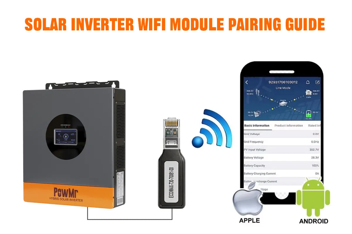
The solar inverter WiFi module connects the inverter to a mobile app or cloud platform, allowing users to monitor the system status anytime and anywhere, including real-time power generation, battery level, and overall system performance.
During actual installation, users often encounter issues such as WiFi connection failure, pairing errors, or the device not being recognized. These problems are usually related to network settings, module compatibility, or incorrect setup procedures.
This guide provides a detailed explanation of how to pair a solar inverter WiFi module, helping users quickly complete the connection and achieve stable and reliable remote monitoring functionality.
What Is a Solar Inverter WiFi Module?
A solar inverter WiFi module, also known as a WiFi module for inverter, is a communication device that connects a solar inverter to a mobile app or cloud monitoring platform. It allows users to remotely access system data through a smartphone, tablet, or computer.
With a WiFi module for inverter, users can monitor real-time power generation, battery status, PV input, and system performance from anywhere. This makes it easier to manage solar energy systems, track energy production, and quickly identify potential solar inverter issues.
How Does Solar inverter WiFi Module Work?
The solar inverter WiFi module is designed to connect the inverter to the internet, enabling remote monitoring and data communication. A WiFi module for inverter is typically connected through RS485, USB, or a dedicated communication port, allowing it to read real-time system data such as power generation, battery voltage, load power, PV input, and overall system status.
How to Connect WiFi Module to an Inverter?
The process of connecting a WiFi module for inverter is usually straightforward, but it must be done correctly to ensure stable inverter monitoring and proper data transmission.
Compatible Inverter Models
Before using a solar inverter WiFi module, it is essential to confirm that your inverter model and communication protocol are compatible. The PowMr WiFi module is not a universal device, and different WiFi modules are designed for specific inverter series. Please make sure to verify compatibility between your inverter model and the WiFi module before purchase. Incorrect matching may result in device recognition failure or communication errors.
PowMr Solar Inverter Compatible WiFi Module Model Table:
| Wi-Fi Module Model | Applicable Inverter Models | Communication Interface | Supported Functions | App |
|---|---|---|---|---|
| WIFI-HF-N |
POW-LVM3K-24V-H、 POW-LVM3.2K-24V、 POW-LVM5K-48V-H、 POW-SunSmart SP5K、POW-SunSmart SP5.2K、POW-SunSmart 6.5KP、 POW-SunSmart 6.5KP-PRO、POW-SunSmart 10K、 POW-SunSmart 10KP、POW-SunSmart 10KP-PRO、POW-SunSmart 12KP、POW-SunSmart 12KP-PRO、 POW-SunSmart 8KL3、 POW-SunSmart 12KL3、POW-SunSmart 12KPL3、 POW-SunSmart LVM12K、 POW-SunSmart 16KP |
RS485 | Remote monitoring, power generation statistics, fault alarm | Solarman (Business version) |
| WIFI-ECO/MAX-730 | POW-HVM10.2M、POW-HVM8.2M、POW-HVM6.2M-48V、POW-HVM6.2M-48V-N、POW-HVM4.2M-24V、POW-HVM4.2M-24V-N、POW-LVM3.6M-24V、POW-HVM3.2H-24V、POW-HVM3.2H-24V-N、POW-HVM2KW-12V | RS485 | Bluetooth network configuration, Wi-Fi configuration, device addition, fault diagnosis | Solar of Things |
| WIFI-RELAB | POW-RELAB 3KU、POW-RELAB 3KE、POW-RELAB 5KU、POW-RELAB 5KE、POW-RELAB 5KU-SPLIT、POW-RELAB 10KU、POW-RELAB 10KE、POW-RELAB 10KU-SPLIT、POW-HVM6.2KP、POW-HVM6.5KP、POW-HVM11KP、POW-HVM12KP | RS232 | Remote monitoring, parameter programming, system status viewing | Solar of Things |
| WIFI-PVS | POW-ECO-3KW、POW-ECO-6KW、POW-PVS-6KW、POW-PVS-10KW | RS232 | Remote control, remote debugging, remote upgrade, data upload | Sun Wise |
WiFi Network Requirements
To ensure successful network configuration and stable online connectivity, your wireless network environment must meet the following requirements:
- Frequency Band: The module only supports the 2.4GHz frequency band (802.11b/g/n) and does not support 5GHz. If your router has "Smart Connect" (dual-band steering) enabled, please disable it in the router settings, or separate the 2.4G and 5G networks into different names, and connect your phone to the 2.4G WiFi beforehand.
- SSID and Password: The WiFi name (SSID) and password must only contain English letters and numbers. Do not use Chinese characters, spaces, or special symbols (such as @, _, -, &, *), otherwise the module may fail to parse the credentials.
- Encryption Mode: Only standard residential WPA/WPA2-PSK encryption modes are supported. WPA/WPA2 Enterprise (which requires a separate username and password) and public networks requiring web-based portal authentication are not supported. If WPA3 is used, please set the router to WPA2/WPA3 mixed mode.
- Network Settings: The router must have DHCP service enabled (to automatically assign IP addresses) and AP Isolation disabled.
- Signal Strength: Please ensure a strong 2.4GHz WiFi signal at the inverter's installation location (e.g., outdoors, garages, etc.). It is recommended to test the location with your phone; the signal strength should display at least 2 to 3 bars.
App Download (iOS / Android)
Please download and install the companion monitoring software using one of the following methods:
- Method 1: Scan the QR Code Use your smartphone (iOS or Android) to scan the QR Code on the device body or the instruction manual to go directly to the download page.
- Method 2: Search in App Stores
-
- For iOS Users: Open the App Store and search for the corresponding app listed in the compatibility table to download.
For Android Users: Open Google Play and search for the corresponding app listed in the compatibility table to download.
- For iOS Users: Open the App Store and search for the corresponding app listed in the compatibility table to download.
Module Port Connection Instructions
To ensure data collection accuracy and hardware safety, please complete the physical connection of the WiFi module while the inverter is in a powered-on or standby state, strictly following the guidelines below:
- Step 1: Identify the Physical Interface The location and type of communication interface vary depending on the inverter model. Please consult your inverter’s manual beforehand to confirm whether it is equipped with an RS232 port or an RS485 port.
- Step 2: Assemble the Cable and Module Take out the WiFi data logger from the packaging box. If a dedicated communication conversion cable is included (commonly provided for specific power-rated models), please first connect this cable to the aviation plug or standard connector of the WiFi module and secure it firmly.
- Step 3: Connect to the Inverter Align the assembled communication cable or the direct plug of the module with the corresponding port (RS232/RS485) on the inverter and insert it. Apply even force to ensure the plug is fully seated. If the interface features retaining screws, tighten them securely to prevent poor contact.
- Step 4: Confirm Power and Communication Status Once connected, the module will automatically draw power through the inverter's port. Closely observe the LED indicators on the module's body (such as COM/NET indicators). If the indicator lights stay constantly on or flash at a specific frequency, it signifies that physical-layer communication between the module and the inverter motherboard has been successfully established.
