Reactive power is the energy required to establish and maintain the magnetic field for inductive load, which are common in everyday life, such as air conditioners, refrigerators, washing machines, and more.
With the popularization of renewable energy power systems, their impact on the utility grid is becoming increasingly significant. Managing reactive power is essential for ensuring the safe and stable operation of both solar power systems and the grid.
In this blog, we will discuss what reactive power compensation is, why it's necessary, its advantages, and how solar inverters contribute to compensating reactive power.
What is reactive power compensation
Reactive power is the portion of electricity that doesn't perform any useful work but is essential for maintaining voltage levels in the power system. It's caused by the phase difference between voltage and current in AC systems, typically due to capacitive or inductive loads.
Reactive Power Compensation/ Reactive Power Regulation / Power Factor Correction, involves improving the power factor of an electrical system by reducing the reactive power drawn from the grid. To maintain grid stability and efficiency, many utility companies enforce a minimum power factor requirement, ensuring balance within the power grid.
Reactive power compensation calculation
Reactive power and power factor can be challenging concepts for those unfamiliar with electrical systems, as they lack clear analogies in the physical world.
Using the power triangle, we briefly explain the relationship between these concepts to help solar system owners better understand them and inspire them to manage their grid-connected solar system’s reactive power in compliance with local grid standards and requirements.
Active power, P, in Watt (W) represents the power used by an electrical device to perform its active work, such as generating light or operating electrical equipment. This can be the sum of the nominal power of the devices.
Reactive power, Q, in VAr, as mentioned above, is the power produced in electrical circuits with inductive loads. It represents the extra energy needed to establish magnetic field and keep them running, even though it does not perform any useful work.
Apparent power, S, in VA is the combined measure of active and reactive power. In electrical systems, it is calculated by multiplying the root-mean-square (RMS) current by the root-mean-square voltage in an AC circuit.
Power Factor (PF) is a measure of how effectively electrical power is being used. It is the ratio of active power (P) to apparent power (S), i.e., PF = P/S, which can be viewed as cosφ (Adjacent side divided by the Hypotenuse).
Reactive power compensation inverter in PV system
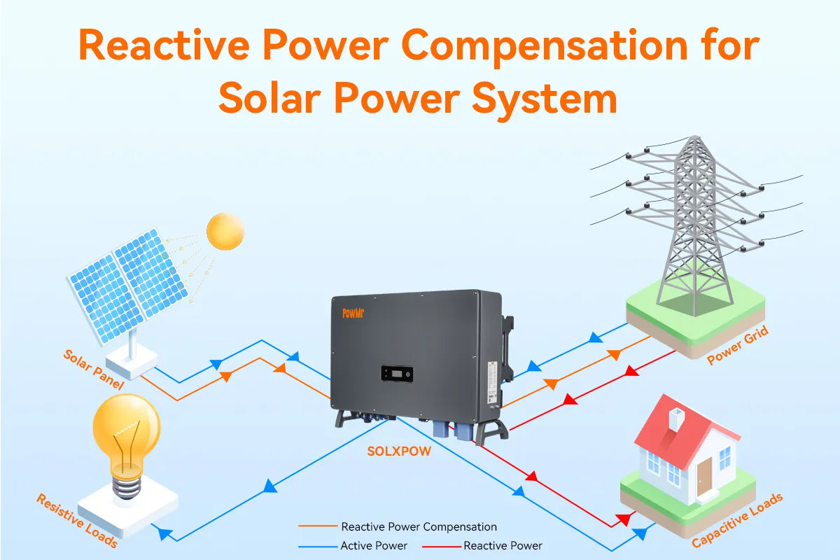
Reactive power issues are common in grid-tied solar systems, frequently observed in residential, commercial, and industrial installations. This is mainly due to the presence of numerous inductive electrical devices within the system. While the power output from the PV system reduces the grid's active power, reactive power continues to be drawn from the grid, leading to a decrease in the power factor.
To prevent the negative impact of reactive power on grid voltage stability and power factor, various local governments and power suppliers have established regulations for grid-tied solar systems. In response, solar inverter manufacturers have developed technology to regulate reactive power in compliance with these different regulations.
In this context, we’ll use the SOLXPOW energy storage inverter as an example to demonstrate how to manage reactive power in a grid-tied solar system.
Solar inverter reactive power control methods
The SOLXPOW inverter corrects reactive power to ensure compliance with various grid standards.
This setting allows the user to configure a fixed reactive power ratio within the range of 0 to 60% (capacitive) or 0 to -60% (inductive) of the inverter's rated power. The system will then absorb or compensate reactive power based on the specified ratio.

Advantages of reactive power compensation
Reactive power compensation in a solar power system offers several benefits:
Compliance with grid code and saving on electricity bills
Many utilities require solar installations to manage reactive power to ensure grid stability. They assess the power factor of the system, and if it falls below their standards, penalties or extra charges for power adjustment may apply. Improving the power factor through reactive power compensation helps avoid these additional costs and reduce electricity bills.
Improve voltage stability and power quality
Effective management of reactive power stabilizes voltage levels, minimizing fluctuations that can damage equipment and cause inefficiencies. It also reduces voltage drops and harmonic distortion, leading to cleaner and more reliable power delivery.
Increase system efficiency
By reducing losses in power lines, reactive power compensation enables more efficient transmission and distribution of electricity, lowering operational costs and enhancing overall system performance.