When connecting multiple lithium batteries in parallel, some batteries require DIP switch settings to assign communication addresses and ensure proper Battery Management System(BMS) communication.
In this guide, we’ll explain what a DIP switch is on a lithium battery, how DIP switches work in battery parallel connection, and how to set DIP switches for lithium battery parallel connection, including DIP switch settings for 2, 3, 4, or more batteries.
What Is a DIP Switch on a Lithium Battery?
A DIP switch on a lithium battery is a small bank of toggles on the rear of the battery enclosure (the back of the pack body), connected to the BMS (Battery Management System). Most packs use 4–8 switches, and each one is either ON or OFF. Different ON/OFF combinations create a unique communication address (also called a Pack ID), so the system can identify every battery when you connect multiple packs in parallel.
On energy storage batteries—especially rack mount batteries—the DIP switch does not change voltage or capacity. Its job is to answer one question: which pack is which? Rack mount lithium batteries are often installed as modular units in a cabinet and expanded in parallel. The solar inverter, monitor, or battery communication bus (commonly RS485 or CAN) uses that address to set master/slave roles, read each pack’s status, and coordinate charge and discharge. If two packs share the same address, or the battery DIP switch settings are wrong, you may see communication failures, parallel faults, incorrect capacity readings, or a system that will not start in parallel at all.
Think of the BMS DIP switch as each battery’s ID number. In one parallel group, every rack mount battery needs a unique DIP combination. Packs should usually match in voltage, capacity, and model, then follow the address table in that model’s manual. What a DIP switch does on a LiFePO4 battery can differ by brand, so always use the chart for your exact product—do not copy settings from another battery line.
How DIP Switches Work in Battery Parallel Connection?
When several lithium batteries run in parallel, the solar inverter needs to know which pack is the master and which packs are the slaves. The DIP switch for parallel lithium batteries is what assigns that role.
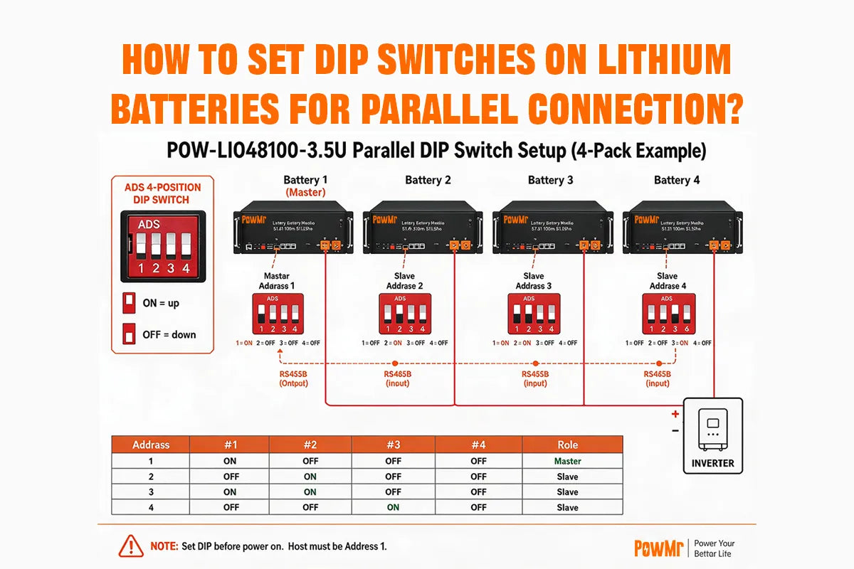
Take the PowMr 100Ah 51.2V Rack Mount Lithium Battery (POW-LIO48100-3.5U) as an example. Give each pack a different address first. The pack linked to the inverter BMS port is the master (address 1); the others are slaves (2, 3, 4…). Connect the packs to each other through RS485B. Then the master reports the full battery group to the inverter over RS485A or CAN.
Remember three rules for battery parallel DIP switch setup:
- No two packs share the same address
- The master must be set to address 1
- Set slaves in order: 2, 3, 4…
If two packs use the same battery DIP switch address, the system cannot tell them apart. You may see the wrong battery count, abnormal status, or a failed parallel connection. On rack mount batteries, set the DIP switches before you finish wiring and power-up checks.
Step-by-Step: Set DIP Switches for Battery Parallel
Taking the PowMr 100Ah 51.2V Rack Mount Lithium Battery as an example, you need to assign a different communication address to each battery before paralleling multiple packs. This battery has 4 DIP switches, and different ON/OFF combinations can set 16 addresses(0–15).
Step 1: Check Voltage Before Wiring
For multi-pack parallel, press each battery’s low-voltage ON/OFF switch and measure voltage with a multimeter.
If voltages match, power off before connecting cables. Do not parallel if voltage difference is too large.
Step 2: Locate the ADS DIP Switches on the Rear
On each 100Ah 51.2V Rack Mount Lithium Battery, find the DIP switch (ADS) on the back—4 positions (#1–#4), each ON or OFF.
In parallel mode, use the DIP switches to assign a communication address and define master/slave roles.
Step 3: Set Master/Slave Addresses (Before Power-On)
Per the manual:
- The pack connected to the inverter via the BMS communication cable = host / master
- Set the master to address 1—must be done before power-on
- Set other packs to address 2, 3, 4…; never use address 1 twice
ADS address table (#1–#4):
| Address | #1 | #2 | #3 | #4 |
|---|---|---|---|---|
|
0
|
OFF
|
OFF
|
OFF
|
OFF
|
|
1 (Master)
|
ON
|
OFF
|
OFF
|
OFF
|
|
2
|
OFF
|
ON
|
OFF
|
OFF
|
|
3
|
ON
|
ON
|
OFF
|
OFF
|
|
4
|
OFF
|
OFF
|
ON
|
OFF
|
|
5
|
ON
|
OFF
|
ON
|
OFF
|
|
6
|
OFF
|
ON
|
ON
|
OFF
|
|
7
|
ON
|
ON
|
ON
|
OFF
|
|
8
|
OFF
|
OFF
|
OFF
|
ON
|
|
…
|
…
|
…
|
…
|
…
|
|
15
|
ON
|
ON
|
ON
|
ON
|
Step 4: Connect Parallel Communication (RS485B)
Use the parallel communication cable to link each battery via RS485B From the master’s Output to the next pack’s Input, then continue to packs 3 and 4.
The pack that talks to the inverter must be the master at address 1<.
Step 5: Grounding
Connect each battery’s ground terminal to system ground (ground terminal on the bottom wiring panel).
Step 6: Connect Parallel Power Cables and Inverter
Use red/black parallel cables to join all packs, then connect to the inverter. Check polarity at every step.
For more than 4 packs, use a busbar before the inverter when possible.
Step 7: Connect Inverter BMS Communication
Use the BMS cable to connect the master RS485A or CAN port to the inverter (protocol and pins depend on inverter brand—see manual section 9.6).
Step 8: Power On in Order and Verify Communication
After wiring and DIP settings are complete:
- Turn on the battery side first
- Then start the inverter
- Confirm the inverter reads battery data (SOC, voltage, pack count, etc.)
If battery data appears on the inverter, BMS communication and DIP addressing are likely correct.