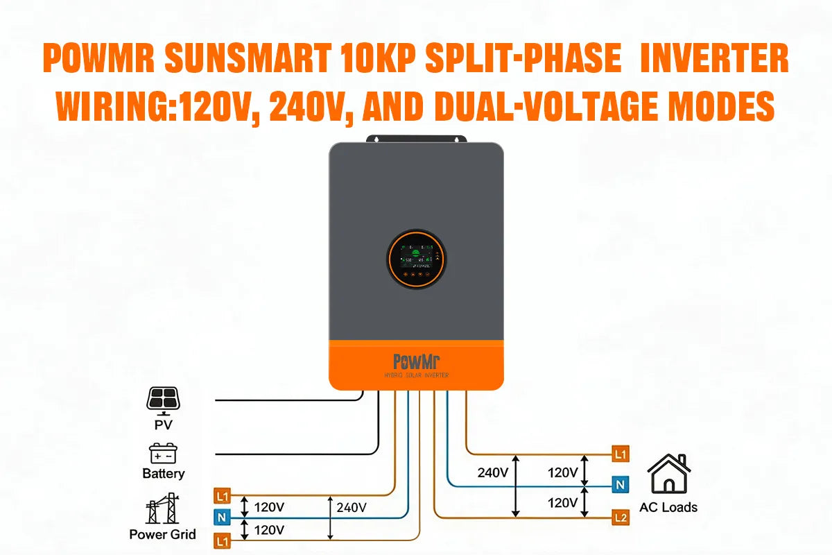
Split-phase inverters can deliver about 120V and 240V, with adjustable phase voltage to match your system. That means one hybrid solar inverter can power everyday 120V household circuits and high-demand 240V appliances.
PowMr POW-SunSmart 10KP split-phase solar inverters are designed for this kind of real-world use. With L1/L2/N output, they can supply U.S.-standard 120V, 240V split-phase, or both at once—and they can also supply European-standard 240V single-phase. In this article, we’ll walk through the three load application modes for the POW-SunSmart 10KP and how to wire each one.
Split-Phase Inverter Output Basics
For off-grid and whole-home backup power systems across North America and standard split-phase grid regions, balancing dual-voltage appliances is a core design priority. Standard household electronics, LED lighting, and kitchen outlets operate on 120V single-phase power, while heavy-duty loads—such as central air conditioning, well pumps, heat pumps, electric clothes dryers, and EV chargers—require a dedicated 240V high-voltage supply.
Traditional single-phase off-grid inverters typically provide only one fixed voltage, often forcing homeowners to install bulky, inefficient external autotransformers to step up or step down power. The PowMr SunSmart series split-phase hybrid inverters eliminate this hardware bottleneck. Engineered with an integrated dual-phase inverter architecture, the SunSmart series natively delivers simultaneous 120V/240V split-phase AC output from a single all-in-one unit—maximizing overall system efficiency and reducing installation footprint.
Understanding Split-Phase Inverter Output Basics
To optimize your solar power system and avoid inverter overloads, it is essential to understand the internal phase architecture and terminal configurations of split-phase inverters.
1. Core Operating Principles of Split-Phase AC Power
The AC output block of the PowMr POW-SunSmart 10KP split-phase inverter features two active hot conductors (L1 and L2), one neutral line (N), and a dedicated ground terminal (PE):
- 180° Out-of-Phase Sine Waves: The sine waves on Phase L1 and Phase L2 are exactly 180° degrees out of phase with each other. When L1 reaches its positive peak, L2 simultaneously reaches its negative peak.
- Phase Voltage (L1-N/L2-N): Measuring the potential difference between either hot line and the neutral wire (L1-N or L2-N) provides a standard nominal voltage of 120Vac, powering conventional residential branch circuits and everyday 120V home appliances.
- Line-to-Line Voltage (L1-L2: 240V): Because the two live legs are 180° opposed, the potential difference between them equals the combined sum of both legs (120 V + 120V = 240 V). This provides clean 240Vac pure sine wave output directly across L1-L2 to handle demanding 240V heavy-duty inductive and resistive loads without external conversion equipment.
2. Configurable Nominal AC Output Voltages
To accommodate varying regional grid standards across the United States, Canada, the Caribbean, and Latin America, the SunSmart series features an adjustable nominal phase voltage setting within its LCD system configuration menu:
Selectable Phase Voltage: 100Vac–130Vac (adjustable in 1V steps; default 120Vac)
Proportional Line-to-Line Outputs: When the phase voltage is configured to 120Vac, the L1-L2-N (split-phase) output operates at 240Vac. If configured to 110Vac, the L1-L2-N (split-phase) output defaults to 220Vac. All technical load breakdowns and power distribution formulas in this guide are based on the standard North American baseline of 120Vac / 240Vac.
Pre-Wiring Preparation for Split-Phase Inverters
Before connecting household loads to the AC output terminals of your PowMr POW-SunSmart 10KP split-phase inverter completing proper pre-wiring checks is essential to ensure electrical safety,prevent overloads, and maximize dual-voltage performance:
- Safety Disconnection Voltage Check: Fully disconnect all power sources, including the PV array disconnect, battery circuit breaker, and AC grid input. After powering off the inverter, wait 5 to 10 minutes to allow the high-voltage internal capacitors to discharge completely. Always verify zero voltage across all AC and DC terminals with a multimeter before removing wiring compartment covers.
- Cable Gauge Neutral Sizing: Size L1, L2, N, and PE for the inverter’s continuous AC output current. Use 6 AWG (≈13 mm²) for SunSmart 10KP split-phase output (or larger if required by local code). Do not downsize the neutral versus L1/L2 under unbalanced 120V loads, and bond PE firmly to the grounding busbar.
-
Circuit Breaker Sizing Isolation:
Between the inverter’s AC output and your critical load subpanel, install a matched overcurrent device. For SunSmart 10KP in Setting 180 split-phase (240V L1–L2), a 3-pole 63A circuit breaker is recommended. If your system is configured as Setting 180 single-phase, or uses NO N or 0, this 63A split-phase recommendation does not apply—follow the breaker size for that wiring mode.
- Phase Balancing Voltage Preset: Audit your load list before terminating wires. Distribute your 120V branch circuits evenly across Phase L1 and Phase L2 to avoid single-phase overload limits, while reserving dedicated circuits across L1–L2 for heavy 240V appliances. Finally, verify the nominal phase voltage setting on the LCD menu is configured to 120Vac (delivering line-to-line 240Vac).
Three Load Application Modes for Split-Phase Inverters
The AC output block of the PowMr POW-SunSmart 10KP split-phase inverter features two hot lines (L1 and L2), one neutral terminal (N),and a protective ground (PE). With the nominal phase voltage set to standard 120Vac the system supports three flexible wiring application modes to supply both everyday branch circuits and heavy-duty 240V equipment without requiring external transformers.
Mode 1: Pure 120V Loads (L-N Configuration)
- Connect L1 and L2 in parallel (bridged/shorted together). Connect the load across the combined L1/L2 and N for 120Vac nominal output at Option 0, enabling full rated power.

Power Output & Best Applications:
Ideal for standard household branch circuits,ighting, televisions, refrigerators,and 120V kitchen appliances.
In this configuration, the inverter's capacity is split evenly across both legs. For example, on a 10KP SunSmart unit, each 120V circuit has a rated power limit of up to 5,000W.
Tip: Balance your 120V loads as evenly as possible between L1 and L2 to minimize return current through the neutral wire and prevent single-phase overload trips.
Mode 2: Pure 240V Loads (L1-L2 Configuration)
Wiring Connection
- Connect the load directly across L1 and L2 for European single-phase 240Vac nominal supply. The neutral wire (N) remains disconnected from this circuit.
Power Output & Best Applications
Designed for dedicated high-voltage residential and light-commercial equipment,including central heat pumps, well pumps,electric clothes dryers, and EV chargers.
n this mode, the inverter can utilize its full rated output capacity through the L1–L2 line-to-line terminals—delivering up to 10,000W on a 10KP model in clean pure sine wave power.
Mode 3: Dual 120V & 240V Simultaneous Mode (Mixed Voltage)
Wiring Connection
- Connect 120V circuits across L1 and N(or L2 and N).
- Connect 240V circuits across L1 and L2

Understanding Power Distribution
In simultaneous dual-voltage mode, the available capacity is governed by the individual power limit of each 120V phase leg rather than a basic sum of the two loads.
Because a 240V (L1-L2) load draws power equally from both phases,the remaining 240V capacity is determined bytwice the remaining headroom on the active 120V leg
Example A On a 10KP solar inverter (5,000W per leg), if L1–N powers a 2,000W 120V load, Phase L1 has 3,000W of capacity left. The maximum rated power available across L1–L2 becomes 6,000W(2 × 3000W).
Example B If the 120V load on L1–N increases to 3,000W Phase L1 has 2,000W remaining, limiting the simultaneous 240V output on L1–L2 to 4,000W(2 × 2,000W).
This simultaneous configuration makes the POW-SunSmart 10KP an all-in-one solution for whole-home off-grid power, eliminating the cost, bulk,and idle losses of external autotransformers.