Da die Leistung eines einzelnen Wechselrichters zunehmend nicht ausreicht, um hohe Lastanforderungen zu erfüllen, hat sich der Parallelbetrieb von einphasigen Wechselrichtern als praktische Lösung etabliert.
Durch die Synchronisation mehrerer Wechselrichter mit identischen Spezifikationen ermöglicht diese Technologie eine Leistungserweiterung bei gleichbleibender Ausgangsspannung und bietet einen flexiblen und zuverlässigen Erweiterungsweg für Wohn-, kleine Gewerbe- und Inselanlagen.
Dieser Leitfaden verwendet den POW-ELITE 10.6KW Serienwechselrichter als Beispiel, um systematisch die Betriebsprinzipien, Verkabelungsstandards und Inbetriebnahmeverfahren für den einphasigen Parallelbetrieb zu erklären, sodass Techniker Mehrfacheinheiten sicher und effizient installieren können.
Was ist der Parallelbetrieb von einphasigen Wechselrichtern?
Der Parallelbetrieb von einphasigen Wechselrichtern bezieht sich auf das Verbinden von zwei oder mehr einphasigen Wechselrichtern desselben Modells und derselben Spezifikationen über parallele Kommunikationskabel. Unter einem gemeinsamen Batteriebank geben die Wechselrichter synchron eine Wechselspannung mit gleicher Phase und Amplitude aus, um gemeinsam Lasten oder das Versorgungsnetz zu speisen.
Aus elektrischer Sicht arbeitet das Parallelsystem ähnlich wie mehrere parallel geschaltete Spannungsquellen. Da die Ausgangsspannung jedes Wechselrichters synchronisiert ist, bleibt die Gesamtspannung des Systems gleich der eines einzelnen Wechselrichters (z. B. 220V/230V), während der Gesamtstrom die Summe der Ströme aller Wechselrichter ist. Dadurch kann die Gesamtleistung gemäß folgender Formel erweitert werden:
Gesamtleistung = N × Leistung eines einzelnen Wechselrichters
Die POW-ELITE 10.6KW Serie Wechselrichter verwendet eine Master-Slave Parallelarchitektur. Ein Wechselrichter ist als „Master“ konfiguriert und verantwortlich für die Erzeugung von Synchronisationssignalen, während die übrigen Einheiten als „Slaves“ betrieben werden, die kontinuierlich ihre Ausgangsleistung an die Master-Einheit anpassen. Über einen Hochgeschwindigkeits-Kommunikationsbus (RS-485/CAN) halten alle Wechselrichter eine Phasensynchronisation mit Millisekunden-Genauigkeit aufrecht, wodurch Umlaufströme aufgrund von Spannungsunterschieden effektiv verhindert werden.
Warum Parallel-Wechselrichter? — Vorteile und Anwendungen
Die Entscheidung, den Parallelbetrieb von Wechselrichtern gegenüber einer einzelnen Hochleistungs-Einheit zu wählen, wird hauptsächlich durch die folgenden Vorteile bestimmt:
| Vorteile | Beschreibung | Anwendungsszenarien |
|---|---|---|
| Flexible Erweiterung | Beginnen Sie mit einem Gerät und fügen Sie bei Bedarf weitere hinzu, um hohe Anfangsinvestitionen zu vermeiden | Leistungsstarke Wohngebäude: Villen, große Wohnungen mit Spitzenlasten über 10kW |
| Leistungsstapelung | Bis zu 6 POW-ELITE 10.6KW Geräte parallel für 63,6kW Gesamtleistung | Kleinhandel & Industrie: Geschäfte, Kliniken, kleine Fabriken mit Einphasenversorgung und hohem Leistungsbedarf |
| Redundanz-Backup | System läuft weiter, wenn ein Gerät ausfällt; kein Single Point of Failure | Notstromversorgung: kritische Einrichtungen, die N+1-Redundanz für unterbrechungsfreie Versorgung verlangen |
| Einfache Wartung | Einzelne Geräte können für Wartung abgeschaltet werden, ohne das Gesamtsystem zu beeinträchtigen | Inselanlagen: abgelegene Gebiete, die unabhängige Stromversorgung mit hoher Kapazitätsreserve benötigen |
| Einphasen-Netzkompatibel | Kein Upgrade auf dreiphasigen Netzanschluss erforderlich, spart Genehmigungskosten | Alle Szenarien, in denen ein dreiphasiger Netzausbau unpraktisch oder kostspielig ist |
PowMr Wechselrichter mit Parallelbetrieb
| Modell | Nennleistung | Batteriespannung | Ausgangsspannung | Max. Anzahl paralleler Geräte | Hauptmerkmal |
|---|---|---|---|---|---|
| POW-SunSmart 10KP-PRO | 10kW | 48V | 110/240V (Geteilte Phase) | 6 | Geteilte Phasenausgabe |
| POW-HVM11KP | 11kW | 24V | 220V | 9 | Hohe Leistung von 24V Batterie |
| POW-SunSmart SP5.2K | 5,2kW | 48V | 110V | 6 | 110V Ausgang |
| POW-SunSmart 8KP | 8kW | 48V | 110/240V (Geteilte Phase) | 6 | Geteilte Phasenausgabe |
| POW-ELITE10.6KW | 10,6kW | 48V | 220V | 9 | Hohe Kapazität, bis zu 9 Geräte |
| POW-ELITE6.6KW | 6,6kW | 48V | 220V | 9 | Bis zu 9 Geräte parallel |
| POW-SunSmart 12KP-PRO | 12kW | 48V | 110/240V (Geteilte Phase) | 6 | Geteilte Phasenausgabe |
Die obige Tabelle zeigt nur ausgewählte repräsentative Modelle. Für eine vollständige Liste der PowMr Wechselrichter, die Parallelbetrieb unterstützen, besuchen Sie bitte die offizielle Webseite.
Parallelvorbereitung vor der Installation
Die wichtigste Voraussetzung für den Parallelbetrieb ist strikte Modellkonsistenz. Die POW-ELITE-Serie verwendet eine Master-Slave-Kommunikationsarchitektur, bei der Daten über den CAN-Bus zwischen den Geräten ausgetauscht werden.
Nur wenn alle Wechselrichter dieselbe Hardwareplattform und Firmware-Version haben, kann eine stabile Phasensynchronisation und Stromverteilungskontrolle erreicht werden. Unterschiedliche Firmware-Versionen lösen Fehler 71 aus, ungleichmäßiger Ausgangsstrom Fehler 72/85.
| Prüfpunkt | Anforderung | Verifizierungsmethode |
|---|---|---|
| Modellkonsistenz | Alle drei Geräte müssen dasselbe Modell sein (z. B. alle POW-ELITE 10.6KW) | Überprüfen Sie den Modellcode auf dem Typenschild des Geräts |
| Firmware-Version | Muss vollständig identisch sein | LCD-Menü: Einstellungen → Info → Firmware-Version |
| Hardware-Version | Empfohlen, identisch zu sein | Kontaktieren Sie den technischen Support von POWMR zur Bestätigung |
| Parallelfunktion | Bestätigen Sie, dass der Parallelbetrieb unterstützt wird | Überprüfen Sie, ob die „Parallelfunktion“ in der Spezifikation mit „Ja“ markiert ist |
Werkzeug- und Materialliste
Bereiten Sie vor der Installation die folgenden Gegenstände vor:
| Kategorie | Empfohlene Artikel |
|---|---|
| Inhalt des Wechselrichterpakets | Wechselrichtereinheit, parallele Kommunikationskabel (RJ45), Stromverteilungskabel, Montageschrauben & Platte, Software-CD, Handbuch, WLAN-Antenne |
| Kabel (pro Wechselrichter) | Batterie: 1/0 AWG (10,6 kW); Wechselstrom Ein-/Ausgang: 8 AWG (10,6 kW); PV: 12 AWG (10,6 kW) |
| Schutzschalter (pro Wechselrichter) | Batterie: 220 A/70 VDC (10,6 kW); Wechselstrom-Eingang: mindestens 50 A |
| Übliche Werkzeuge | Schraubendreher, Drehmomentschlüssel (1,2–5 Nm Bereich), Abisolierzange, Multimeter, Sammelschienen oder Verbinder für parallele Kabel |
| Schutzausrüstung | Isolierte Handschuhe, Schutzbrille, Voltmeter |
Anforderungen an die Installationsumgebung
- Montagefläche: Vertikale Beton- oder andere nicht brennbar Wand mit Tragfähigkeit (Brandgefahr-Warnung laut Handbuch).
- Freiraum: Erlauben Sie 50 cm oben/unten und 20 cm an jeder Seite für Wärmeabfuhr; halten Sie 100 cm Freiraum vorne für Zugang.
-
Umweltgrenzen:
- Temperatur: -25 °C bis +60 °C (optimale Betriebsbedingungen)
- Luftfeuchtigkeit: 0–95 % relative Luftfeuchtigkeit (nicht kondensierend)
- Höhe: ≤ 2000 Meter
- Standort: Geschatteter, regengeschützter Bereich, nicht in direktem Sonnenlicht, fern von brennbaren Materialien oder explosionsgefährdeten Atmosphären.
- Ebene Montage: Für Parallelsysteme sicherstellen Alle Wechselrichter sind auf derselben Ebene installiert (Handbuchanforderung, siehe Anhang I).
Kabelvorfertigung – Das Prinzip der gleichen Länge
Kritische Anforderung: Alle Batteriekabel, die an denselben Batteriebank angeschlossen sind, müssen für jeden Wechselrichter exakt dieselbe Länge haben. Das Handbuch warnt ausdrücklich: „Stellen Sie sicher, dass die Länge aller Batteriekabel gleich ist. Andernfalls entsteht eine Spannungsdifferenz zwischen Wechselrichter und Batterie, die dazu führt, dass parallele Wechselrichter nicht funktionieren.“
So wird es umgesetzt:
Messen Sie die Entfernung vom Batteriebank zum am weitesten entfernten Wechselrichter.
Schneiden Sie alle Batteriekabel (positiv und negativ) auf die maximale Länge zu – auch für näher gelegene Wechselrichter.
Verwenden Sie für jede Einheit denselben Kabelquerschnitt und Kupfermaterial.
Für das gesamte Parallelsystem verwenden Sie eine Sammelschiene, um alle Wechselrichter-Batteriekabel zusammenzuführen, und verbinden dann die Sammelschiene mit dem Batteriebank. Das Kabel von der Sammelschiene zur Batterie sollte das X-fache des Kabelquerschnitts eines einzelnen Wechselrichters haben, wobei X = Anzahl der parallelen Einheiten ist.
Dasselbe Prinzip gilt für Wechselstrom-Ein- und Ausgangskabel – halten Sie die Längen bei allen Wechselrichtern gleich, um Stromungleichgewichte zu vermeiden.
Sicherheitsvorkehrungen und Anforderungen an persönliche Schutzausrüstung (PSA)
Installateure müssen isolierte Handschuhe, Schutzbrillen und isoliertes Schuhwerk tragen. Halten Sie alle Batterie- und Wechselstrom-Schutzschalter während der Verkabelung geöffnet. Überprüfen Sie mit einem Multimeter die Spannung auf Null, bevor Sie die Anschlüsse berühren. Überprüfen Sie die Batteriepole dreifach – eine falsche Polung bei einem Hochstrom-Batteriebank kann den Wechselrichter sofort zerstören. Verwenden Sie nur für Gleichstrom geeignete Schutzschalter; für Wechselstrom ausgelegte Geräte erzeugen Lichtbögen und versagen in Gleichstromkreisen. Ziehen Sie die Anschlüsse mit dem vorgeschriebenen Drehmoment an. Verbinden Sie parallele Kommunikationskabel nur, wenn alle Geräte spannungsfrei sind.
Systemverdrahtung
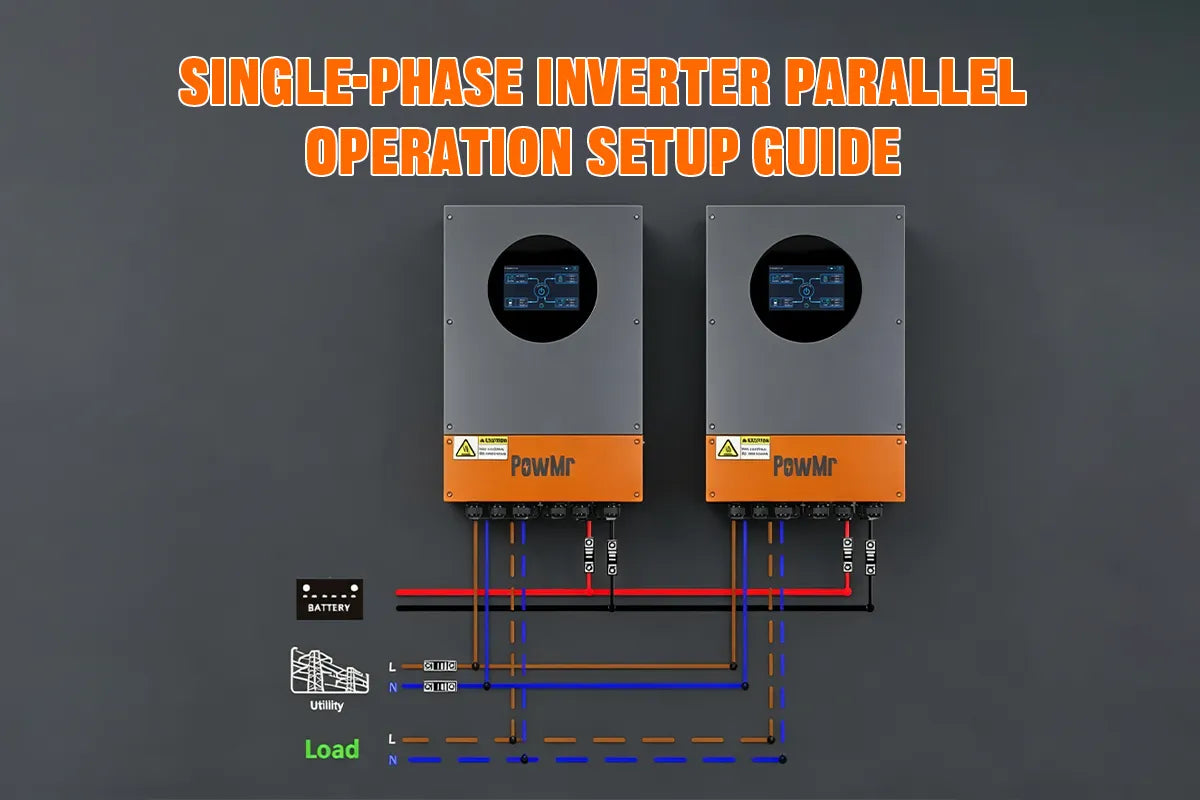
Übersicht Verdrahtungsdiagramm
Die Verdrahtung des Wechselrichter-Parallelsystems folgt dem Prinzip: Schwachstrom vor Starkstrom, Kommunikation vor Leistung. Das gesamte System besteht aus mehreren Wechselrichtern, die sich eine gemeinsame Batterie teilen, wobei jede Einheit unabhängig mit ihrem eigenen PV-Array verbunden ist.
Die AC-Ausgänge werden parallel geschaltet und dann mit dem Netz oder der Last vereinigt. Das POW-ELITE parallele Kommunikationskabel ermöglicht die Master-Slave-Synchronisation über den CAN-Bus, während das Stromverteilungskabel eine ausgewogene Stromverteilung sicherstellt. Vor der Verdrahtung bestätigen Sie, dass alle Schutzschalter geöffnet sind.
Erdungsanschluss
Die Erdung ist der erste kritische Schritt beim Parallelschalten von Wechselrichtern, um die Sicherheit von Personen und den Schutz der Geräte zu gewährleisten. Der PE-Anschluss (Schutzleiter) jedes Wechselrichters muss mit einem separaten Erdungsleiter direkt zu einer gemeinsamen Erdungsschiene oder Elektrode geführt werden. Der Erdungsleiter muss ein gelb-grünes Kupferkabel sein.
Der Gesamtwiderstand der Systemerdung muss den örtlichen Vorschriften entsprechen (z. B. ≤10Ω. oder ≤25Ω. je nach Rechtsgebiet). Schließlich müssen der Batterierahmen, das Gehäuse der AC-Sammelschiene und alle Metallchassis zuverlässig verbunden sein, um eine Potentialausgleichsschleife zu bilden, die das Risiko eines elektrischen Schlags eliminiert und elektromagnetische Störungen (EMI) minimiert.
Paralleles Kommunikationskabel
#1 (Master) → #2 (Slave) → #3 (Slave) → ... → #N (Slave)
AC-Ausgangsverdrahtung
Die AC-Ausgangsseite verwendet eine individuell-zuerst, gemeinsam-danach Struktur. Der AC-Ausgangsanschluss jedes Wechselrichters ist mit seinem eigenen dedizierten AC-Zweigschutzschalter verbunden. Die unteren Anschlüsse aller Zweigschutzschalter sind parallel an eine AC-Sammelschiene angeschlossen. Der Gesamtausgang der Sammelschiene führt dann durch einen Hauptschutzschalter, bevor er mit dem Netz oder der Last verbunden wird.
Für eine einzelne POW-ELITE 10,6KW Einheit wird ein AC-Schutzschalter mit 50A empfohlen. In einem Mehrgeräte-Parallelsystem sollte jede Wechselrichterleitung mit einem eigenen 50A-Leitungsschutzschalter ausgestattet sein, um den individuellen Leitungsschutz zu gewährleisten und eine isolierte Wartung zu ermöglichen. Wenn die Einheiten parallel geschaltet sind, sollte der gesamte Überstromschutz des Systems (z. B. ein Hauptverteilungsschutzschalter) entsprechend der kumulierten maximalen Lastanforderung und den örtlichen elektrischen Vorschriften dimensioniert werden.
Alle Schutzschalter bleiben während der Verdrahtung offen. Sie werden schrittweise während der Inbetriebnahme geschlossen. Die AC-Sammelschiene muss für den gesamten Dauerstrom aller parallel geschalteten Einheiten ausgelegt sein.
Batterieverkabelung (gleiche Länge)
- Nur DC-geeignete Schutzschalter verwenden; AC-Schutzschalter sind streng verboten
- Kabelkennzeichnung muss klar sein, mit unterschiedlichen Farben für Plus und Minus
- Klemmverbindungen müssen sicher sein, mit Drehmoment gemäß Spezifikation
- Polarität vor dem Einschalten mit einem Multimeter überprüfen
PV-Eingangsverdrahtung
Die PV-Eingangsklemmen jedes Wechselrichters sind unabhängig mit ihren jeweiligen PV-Strings verbunden. Die PV-Eingänge mehrerer Wechselrichter dürfen nicht parallel geschaltet werden — dies ist ein entscheidender Unterschied zur Batterieseite und zur AC-Ausgangsseite des Parallelsystems.
- Das Parallelschalten der positiven oder negativen PV-Anschlüsse zwischen verschiedenen Wechselrichtern ist strengstens verboten
- PV-Kabel müssen wetterbeständig sein und die Verlegung im Freien muss den örtlichen Vorschriften entsprechen
- Die Erdungsmethoden der Strings müssen den örtlichen elektrischen Normen entsprechen
- Überprüfen Sie regelmäßig die Wasserdichtigkeit der PV-Steckverbinder
Wechselrichterkonfiguration
LCD-Menünavigation
Der Solarwechselrichter wird über die Touchscreen-Oberfläche an der Frontplatte konfiguriert. Das Standardverfahren erfordert die vollständige Verkabelung – einschließlich Batterie-, AC- und Kommunikationskabel – im vollständig spannungsfreien Zustand. Bringen Sie die Anschlussabdeckungen wieder an und stellen Sie sicher, dass der Erdungsdraht an jeder Abdeckung korrekt angeschlossen ist.
Schließen Sie zuerst den Batterieschutzschalter, um die Einheiten mit Strom zu versorgen, und halten Sie dann die Einschalttaste am Wechselrichter gedrückt, um den Bildschirm zu aktivieren. Die Hauptoberfläche zeigt den wichtigsten Systembetriebsstatus, einschließlich PV-Eingangsleistung, Batteriespannung und AC-Ausgangsleistung. Tippen Sie auf das Einstellungssymbol oben rechts, um das Konfigurationsmenü zu öffnen, und navigieren Sie über die Touch-Oberfläche, um Parameter anzupassen.
Nach der Konfiguration der Paralleleinstellungen und der Bestätigung eines normalen Parallelbetriebs schließen Sie abschließend die PV-Eingangs-, AC-Eingangs- und AC-Ausgangs-Schutzschalter nacheinander, um das gesamte System zu starten.
Parallelmodus einstellen
- Suchen Sie die Option Parallelfunktion oder Arbeitsmodus
- Ändern Sie den Standard Single (Einzeleinhheitsmodus) auf Parallel (Parallelmodus)
- Bestätigen Sie die Systemmeldung, dass der Parallelmodus aktiviert ist
- Einstellungen speichern und auf den Neustart des Wechselrichters warten
Zuweisung der Einheiten-ID (Master/Slave)
Parametersynchronisation
| Parameterkategorie | Spezifische Punkte |
|---|---|
| Batterieparameter | Batterietyp, Nennspannung, Kapazität, Ladestrom, Erhaltungsladespannung |
| Wechselstrom-Ausgangsparameter | Ausgangsspannung, Frequenz, Ausgangsmodus |
| Systemparameter | Parallele Einheitenanzahl, Phaseneinstellung, Netzstandard |