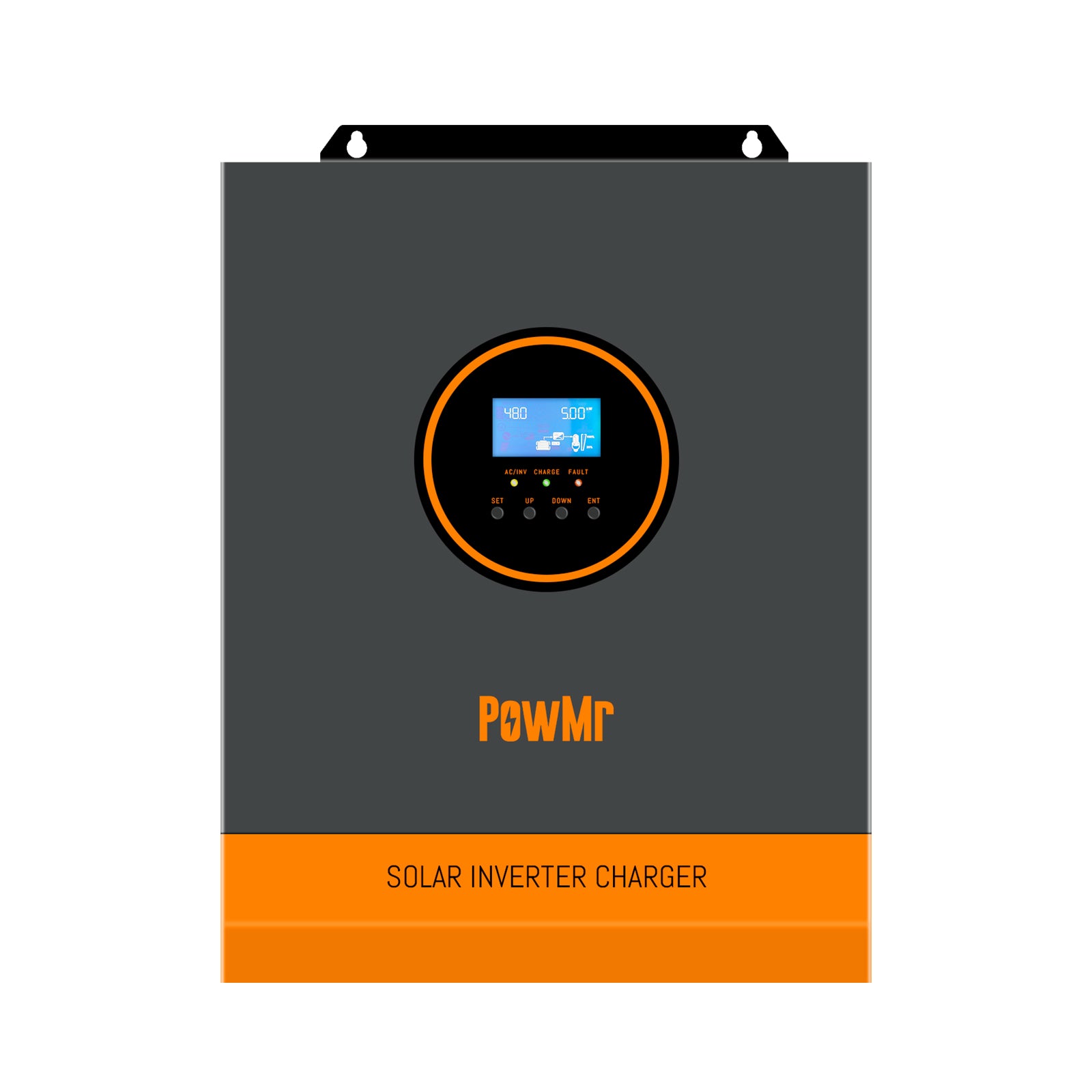
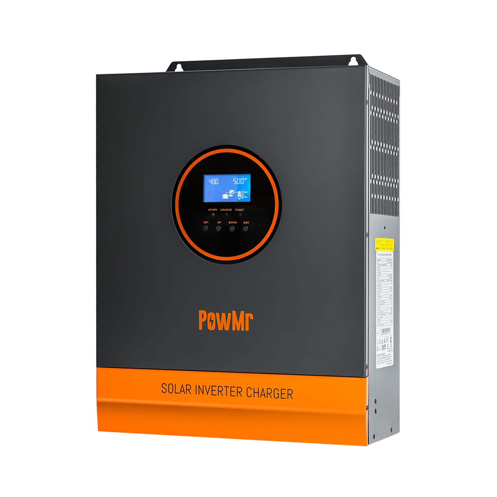
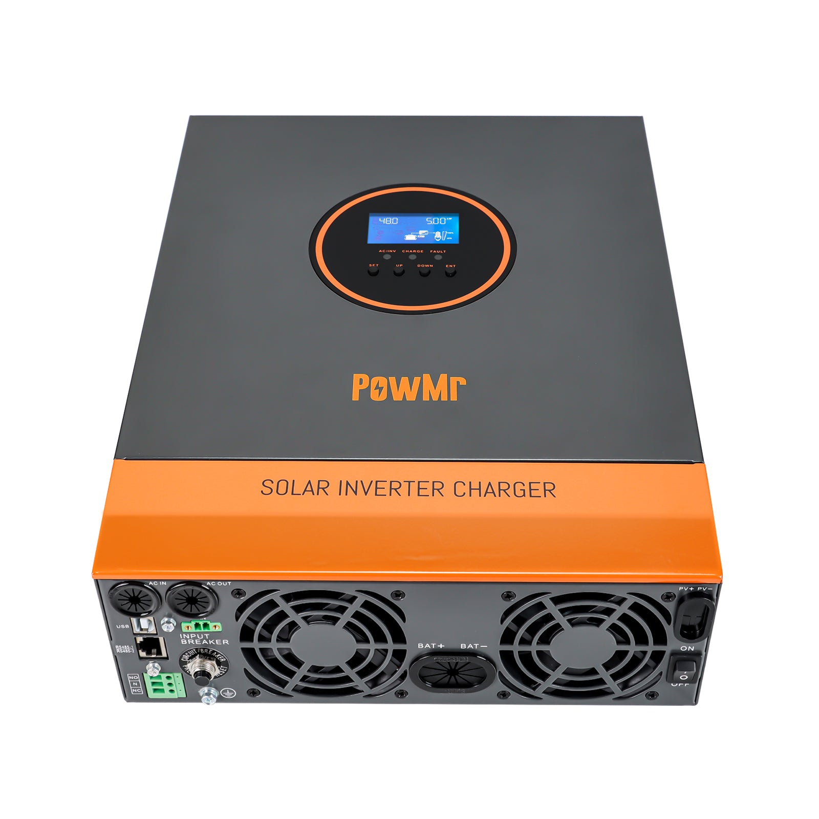
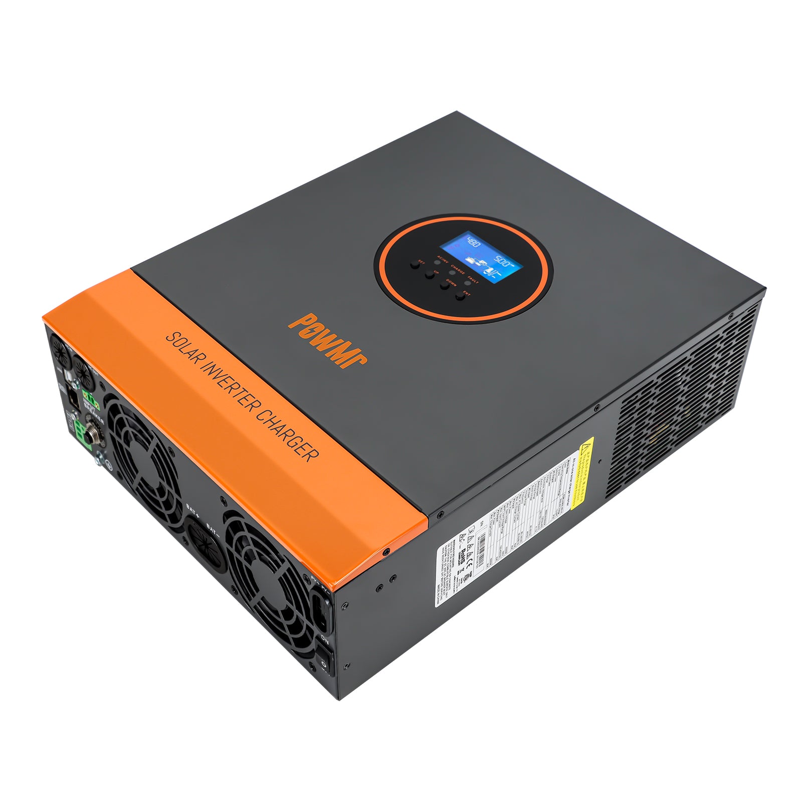
3000W 110Vac 24Vdc All In One Inverter Charger
Shipping
Free shipping to most countries, please consult us if you have any questions.
Warranty
2 year warranty inverters & controllers, 5 year warranty batteries, 15 year warranty solar panels.
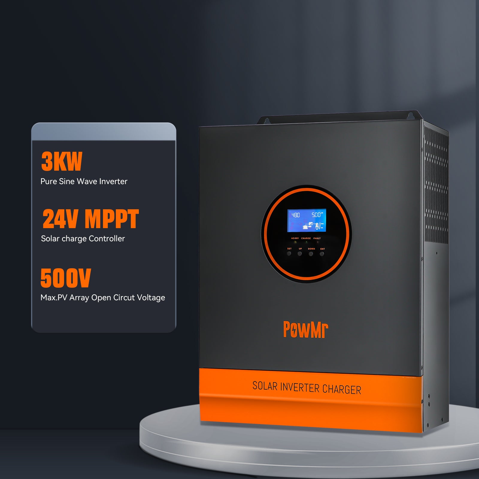
3kW Pure Sine Wave Inverter Charger
Built-In MPPT Solar Charge Controller
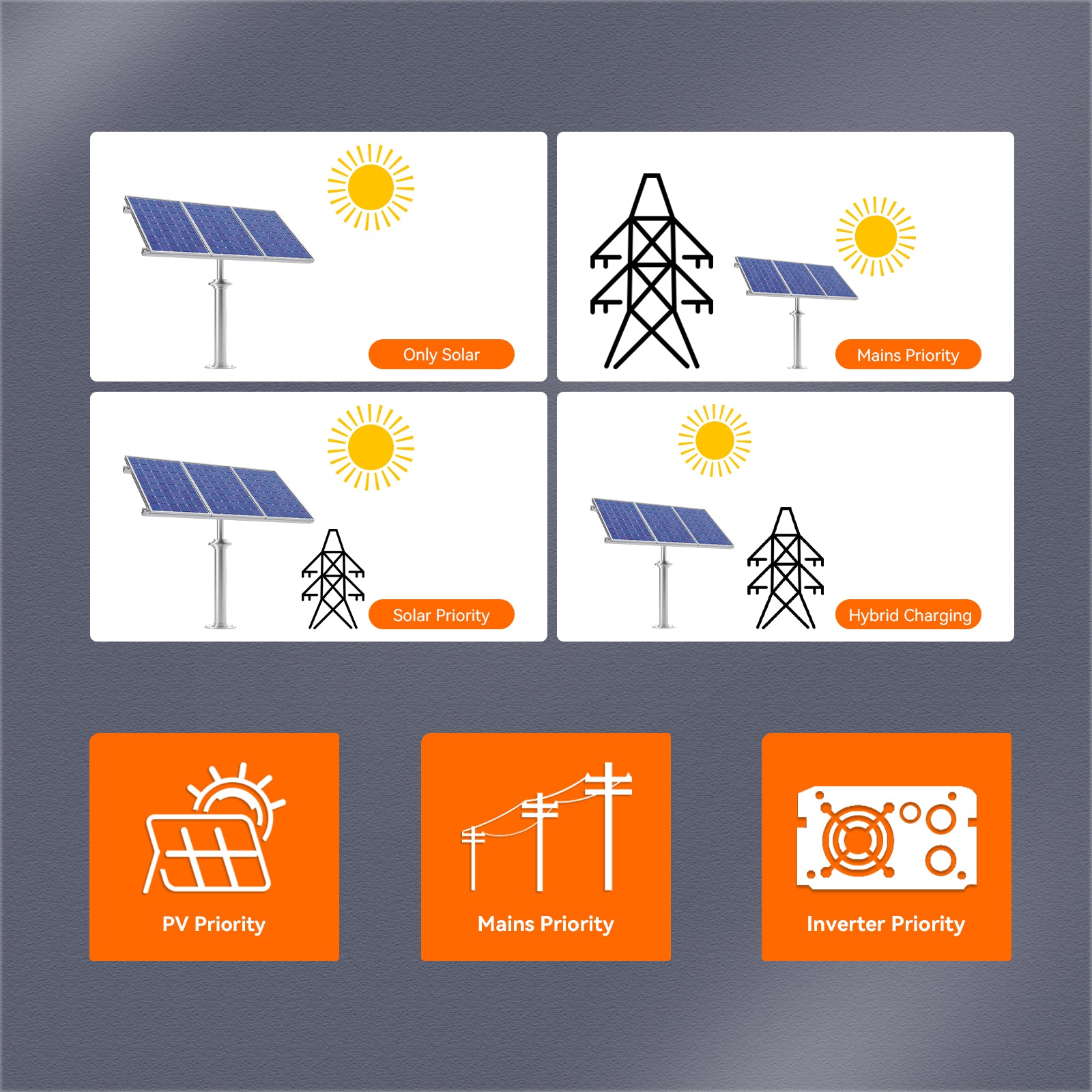
Multiple Charging and Output Modes

Comprehensive Protections
3kW Pure Sine Wave Inverter Charger
Built-In MPPT Solar Charge Controller
Multiple Charging and Output Modes
Comprehensive Protections
PowMr Inverter Charger Specification
Important Notice:
Please Read Product Manual Before Buying. Detailed specifications and features provided. Contact our support team for assistance. Thank you for choosing us.
POW-LVM3K-24V-H
3000Watt
120Vac±5%
24V
Single Phase
120-450Volt (Max. PV Array Open Circuit Voltage: 450V)
4000W
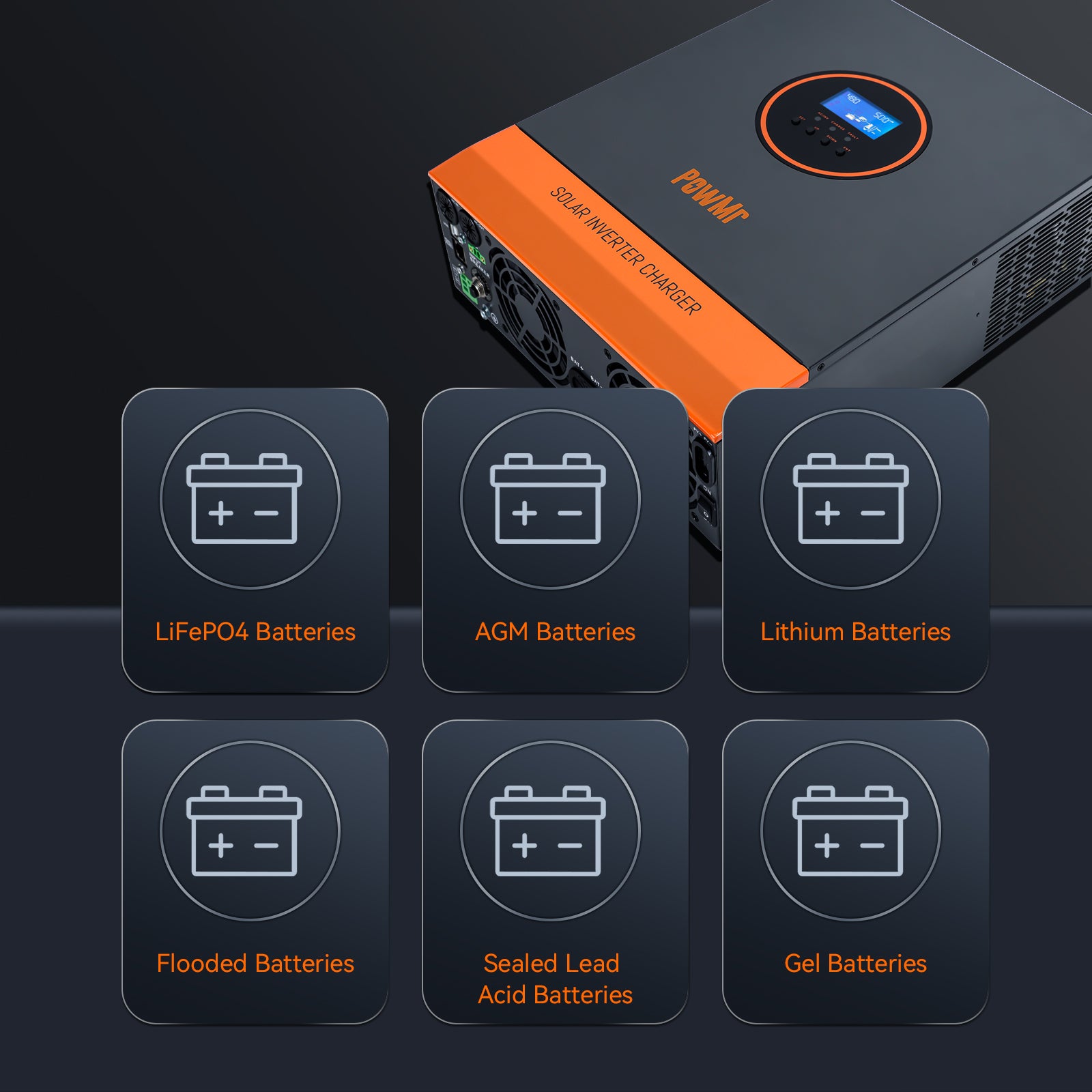
LiFePO4 Batteries, AGM Batteries, Lithium Batteries, Flooded Batteries, User Mode, Sealed Lead Acid Batteries, Gel Batteries
/
This product is rated 4.8 of 5.0 stars.
It has received 4 reviews.
Customer Reviews
My good product quality, the manual is not very detailed about the correct configuration of each item.
I arrived very well, need to try
5 days to bogota Colombia
Thanks

excellent
Works fine, too small cable gauge allowed.