All in One Inverter Chargers
Filters
10 products
3000W 110Vac 24Vdc All In One Inverter Charger


5000W 110Vac 48Vdc All In One Inverter Charger


1600Watt 220Vac 12Vdc All In One Inverter Charger
8000W 230Vac 48Vdc All In One Inverter Charger Supports 6 Units in Parallel
3000Watt 220Vac 24Vdc All In One Inverter Charger


4500W 220Vac 24V All in One Inverter Charger
6500W 48V All in One Inverter Charger
6200W 220Vac 48Vdc All In One Inverter Charger Supports 12 Units in Parallel

1500Watt 220Vac 24Vdc All In One Inverter Charger

1000Watt 220Vac 12Vdc All In One Inverter Charger
Have diversified energy needs?
Find the perfect match for your electricity requirements now!
FAQ
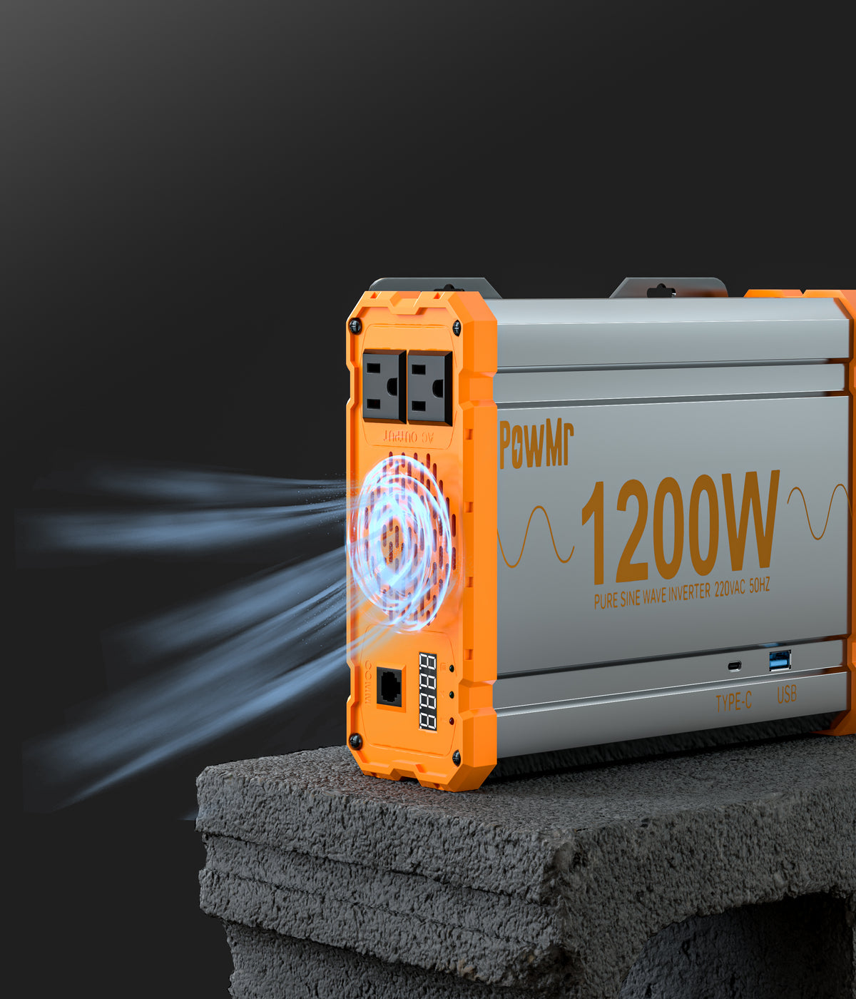
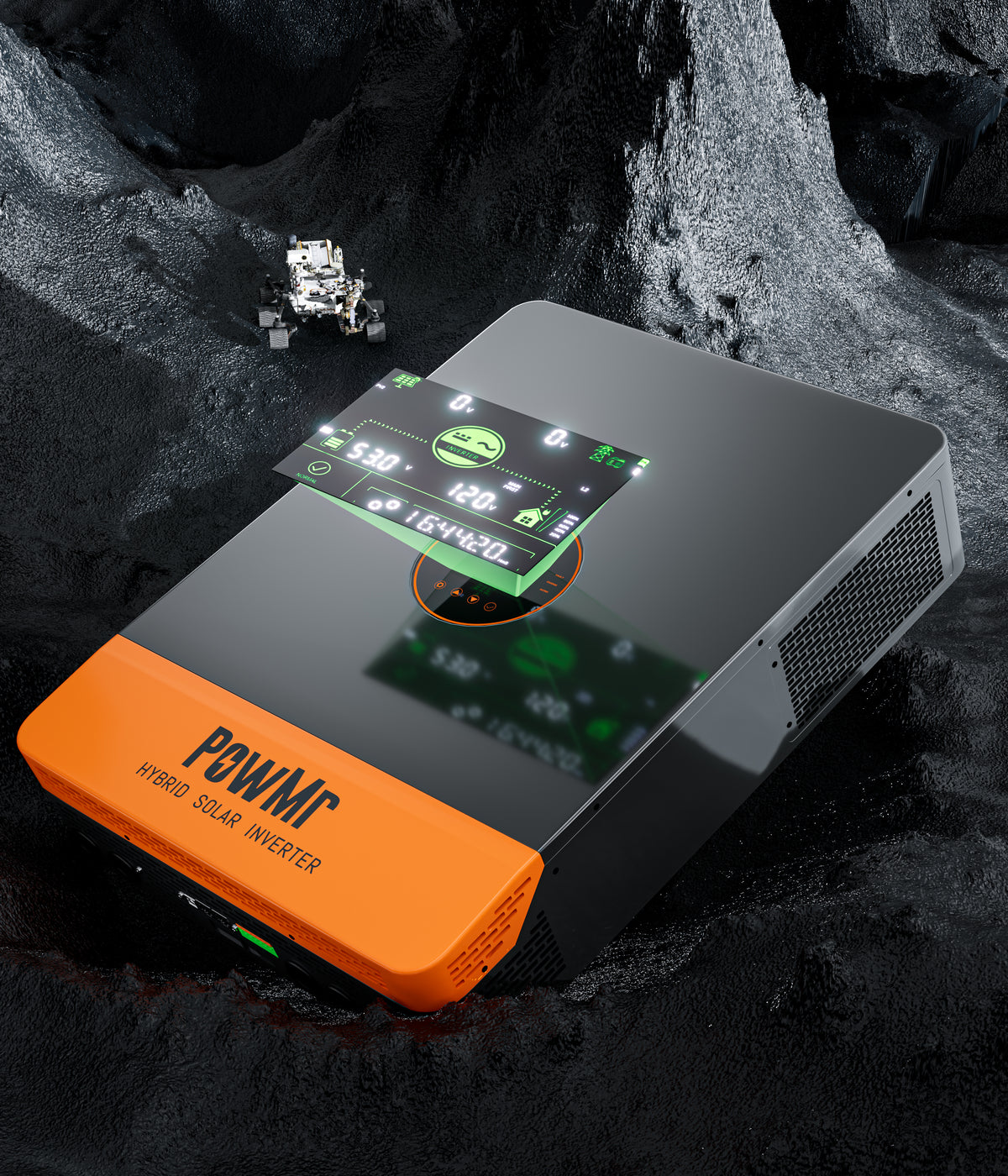
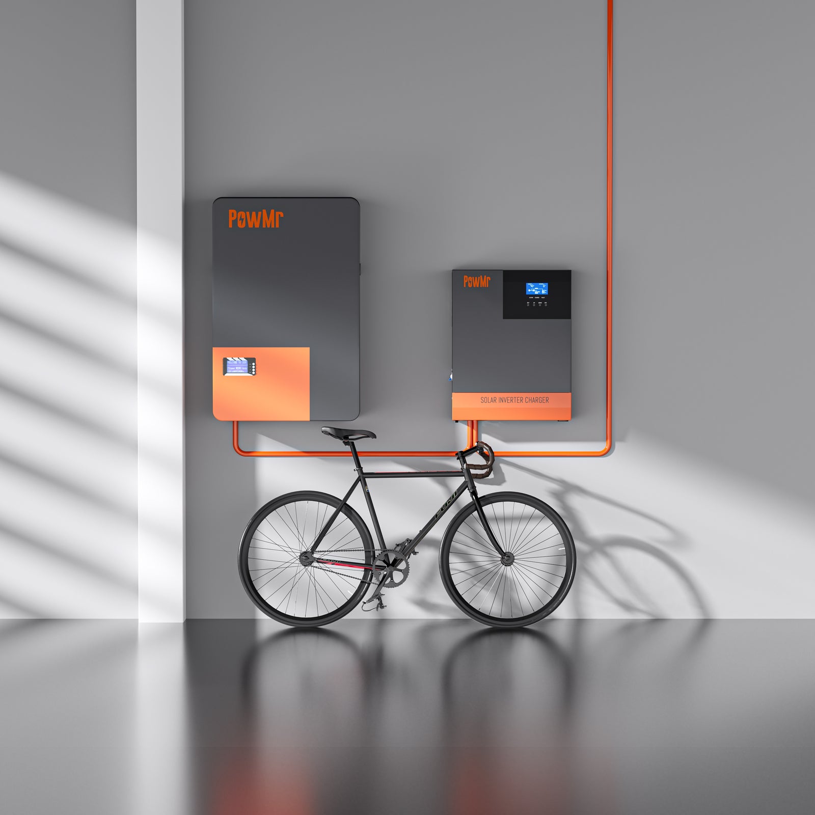
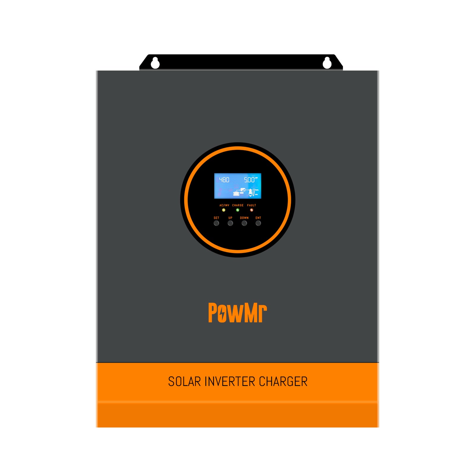
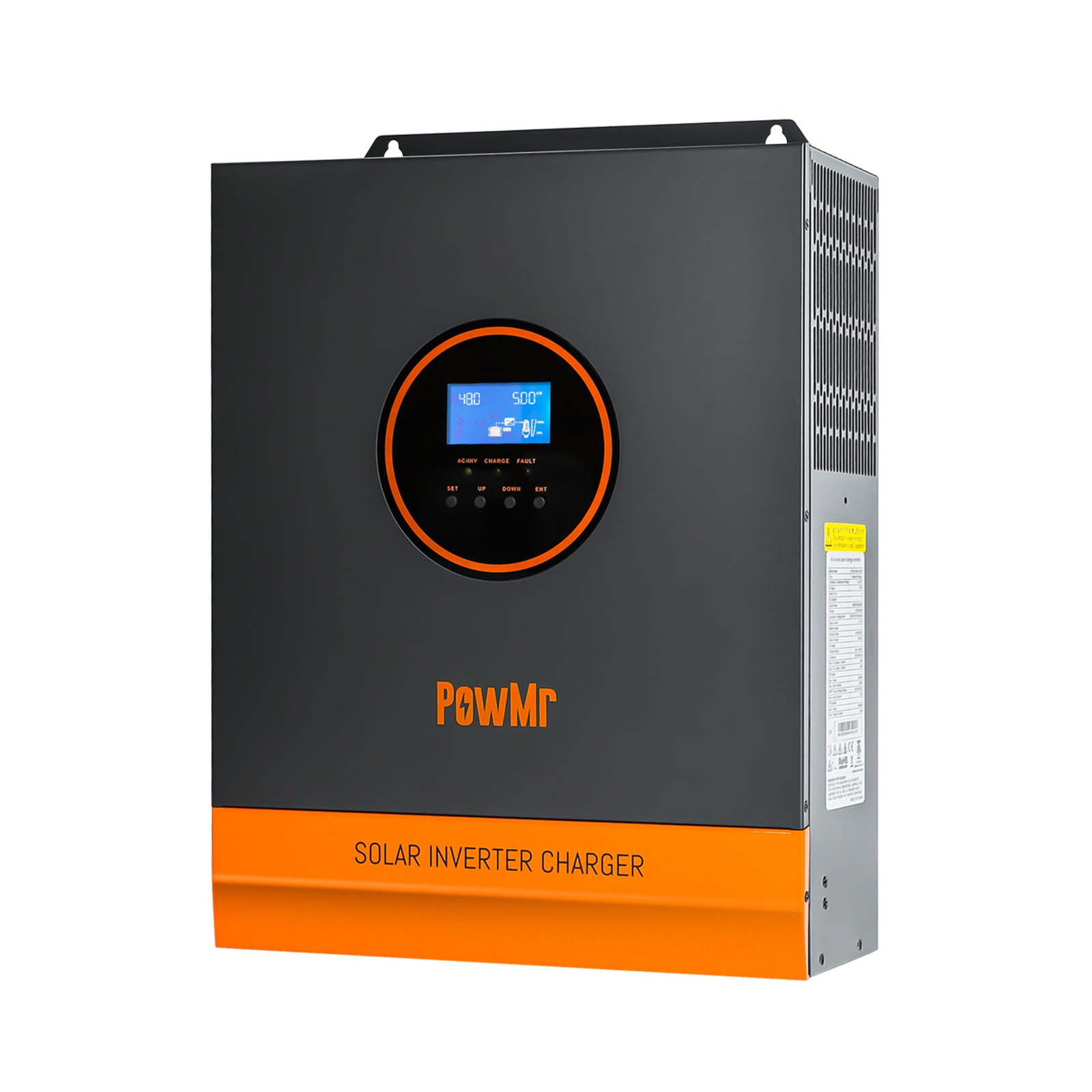
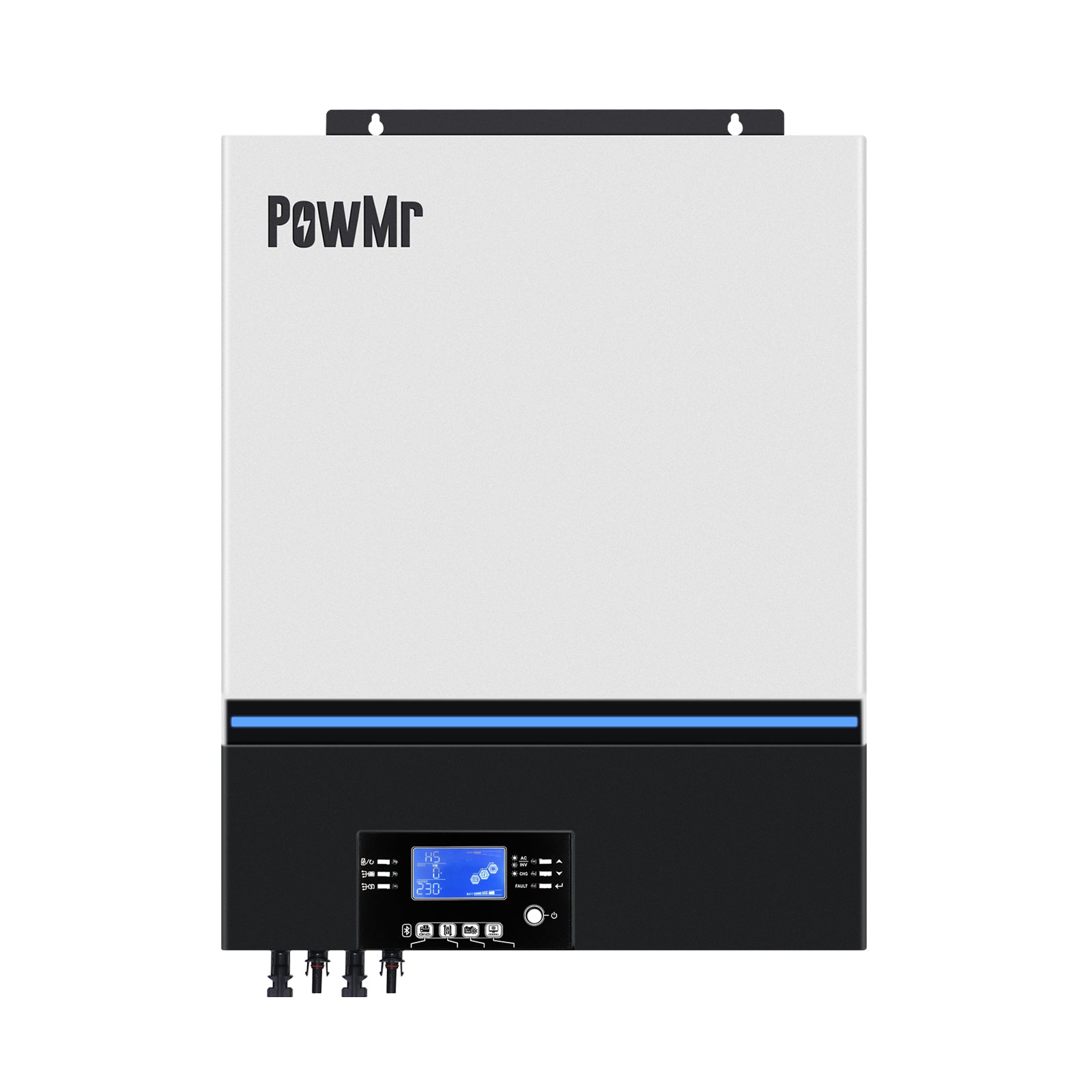
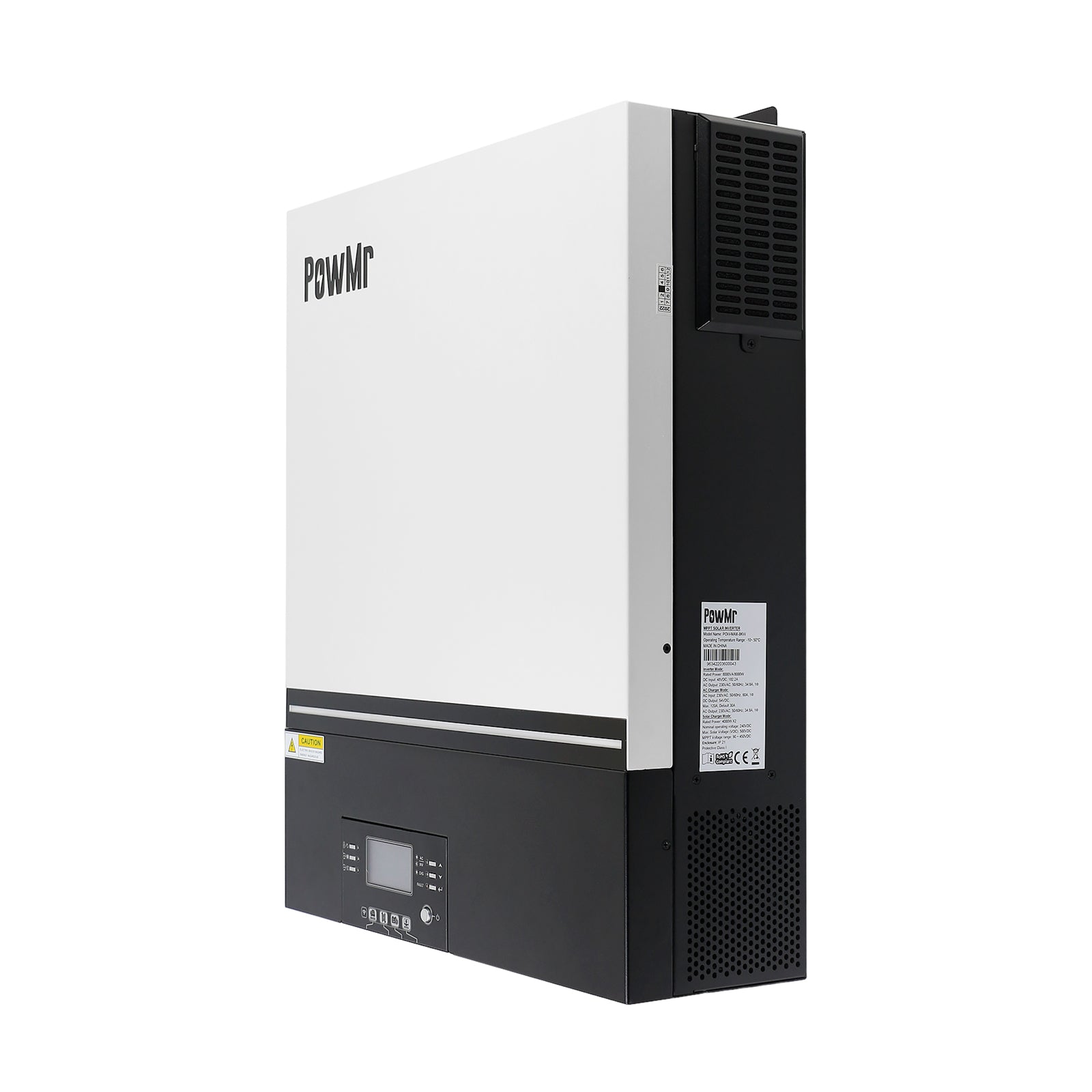
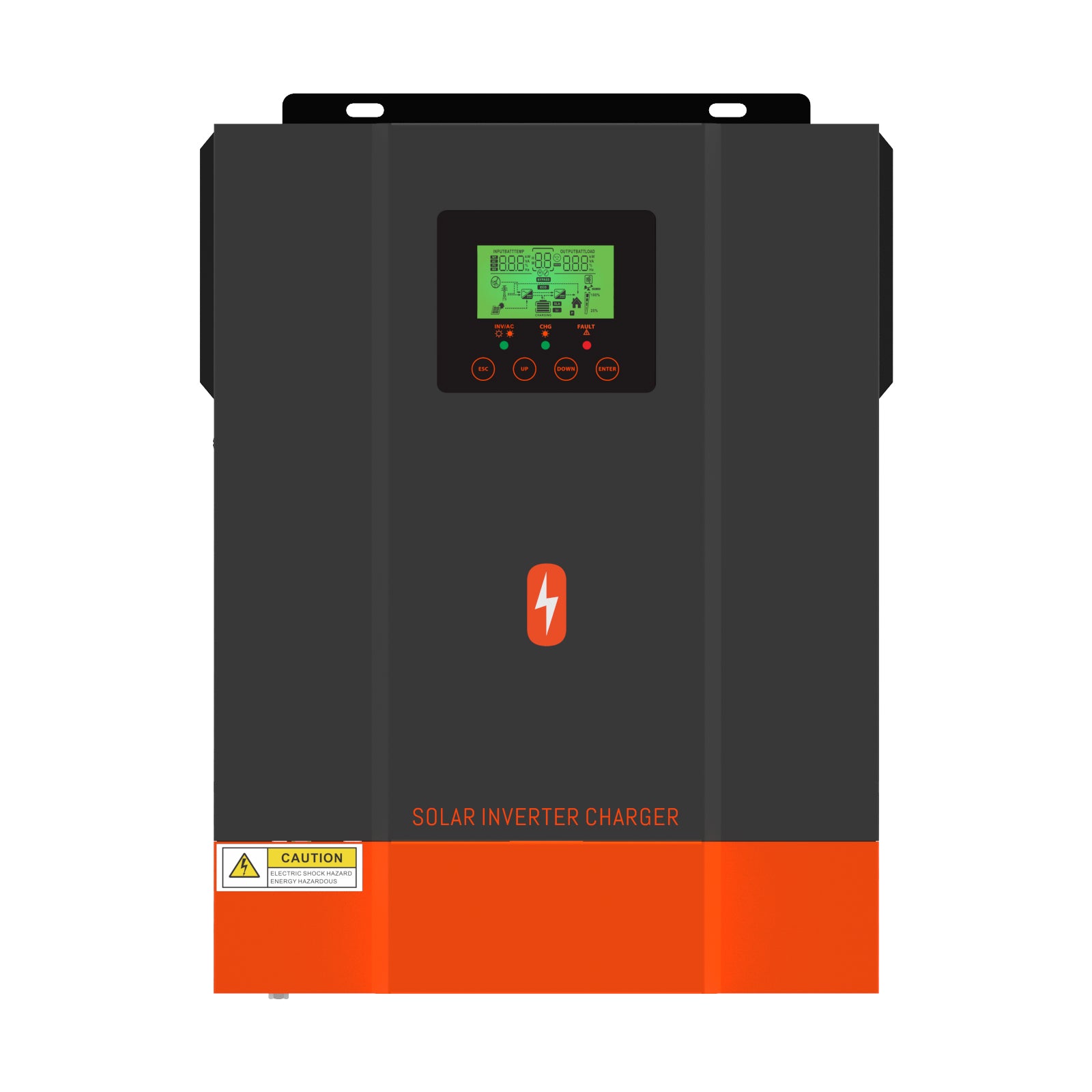
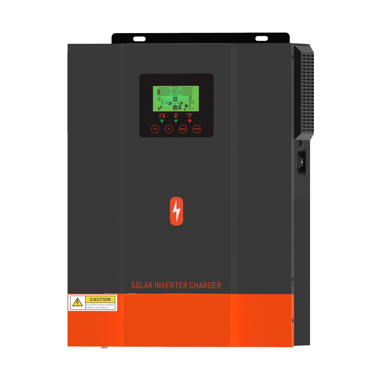
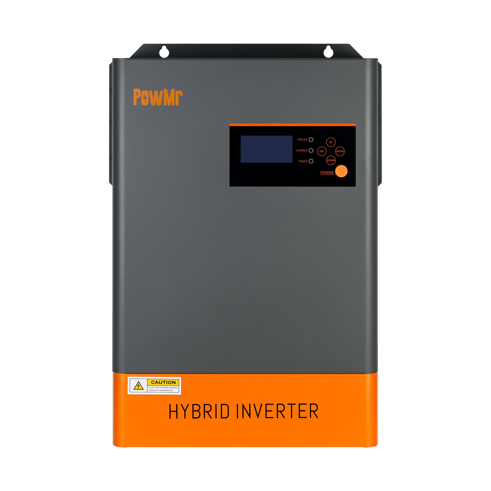
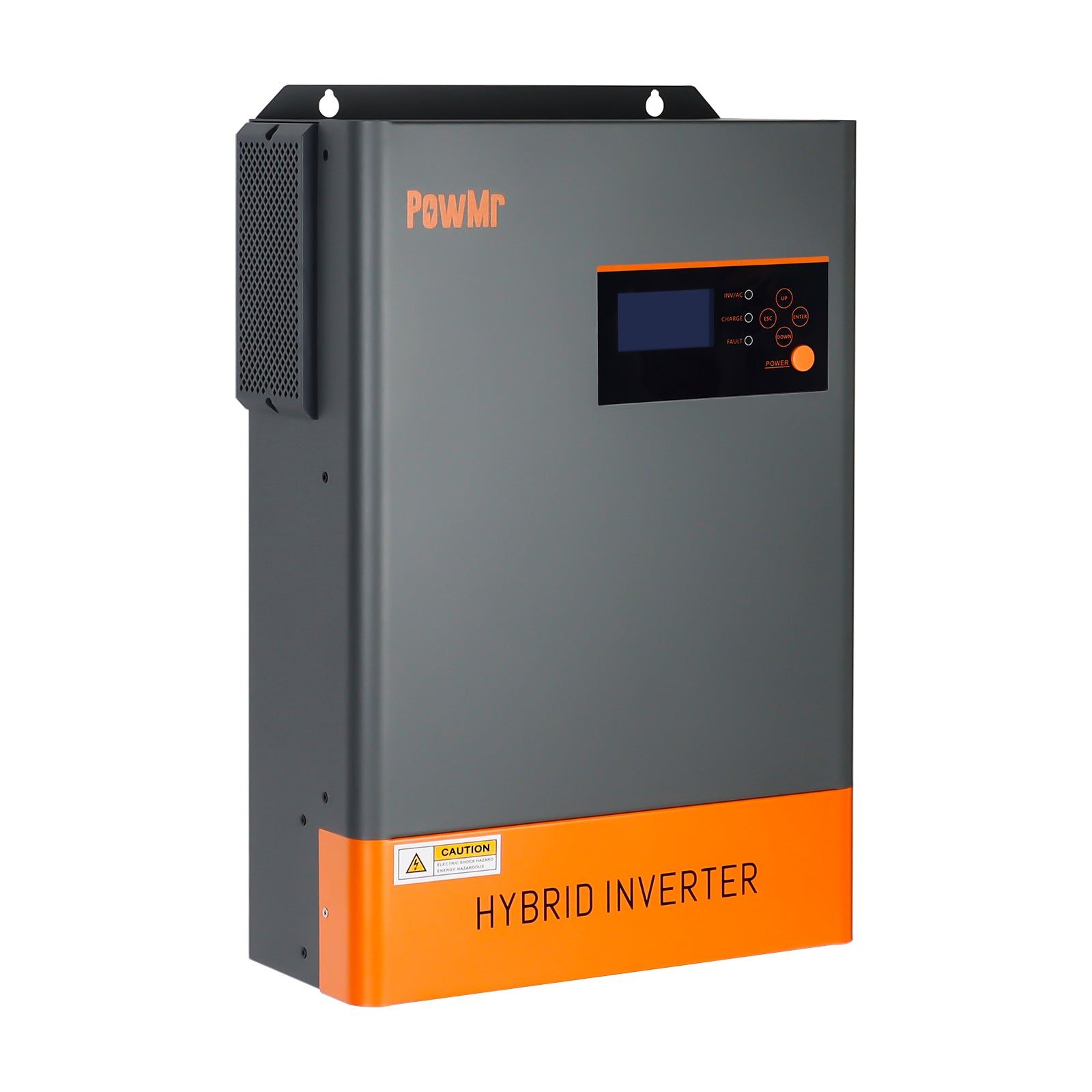
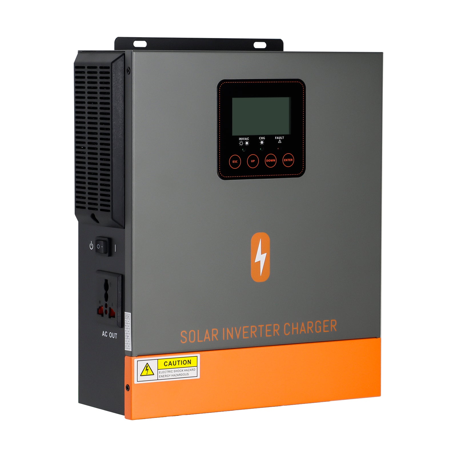
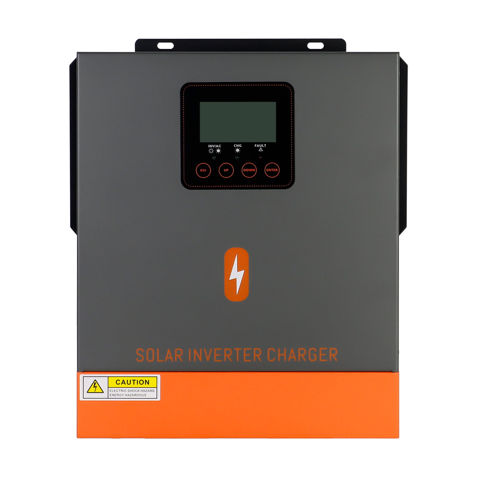
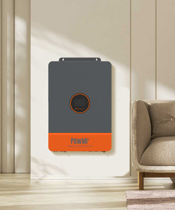
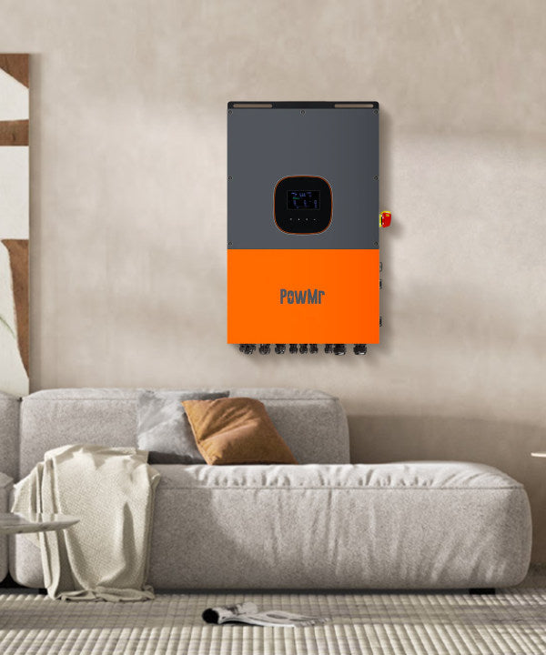
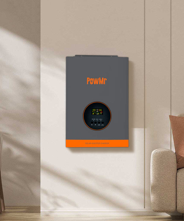
What Is an All in One Inverter Charger?
All in one inverter charger: we also called Solar inverter charger, it has built-in PWM or MPPT solar charge controllers, you can directly use solar energy, AC grid, generator Or a combination of several to charge your batteries. It is a very simple inverter, which is widely used in household solar off-grid systems, RVs, motorboats, etc.
Main Features of All in One Inverter Charger?
Parallel machine: Connect multiple machines of the same brand and model with parallel functions to the same set of batteries, and realize information sharing between the machines through the connection of communication lines.
Phase separation: the function of dividing single-phase power into two-phase or three-phase power.
Lithium battery activation function: This function can activate the dormant lithium battery under the protection of BMS so that it can work normally.